Skived Heat Sinks for IGBT Modules: Selection and Design Considerations
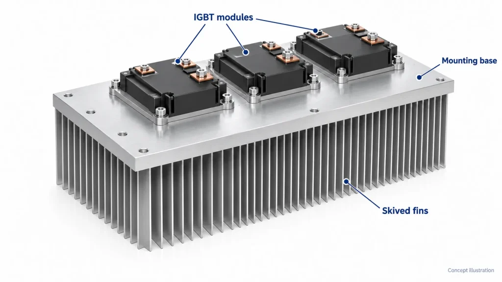
A skived heat sink is worth evaluating for IGBT modules when the required fin geometry is difficult to achieve with extrusion. It is not automatically the better cooler. The choice depends on module losses, available airflow, installation space and the mounting interface.
For an air-cooled inverter, begin with those conditions rather than selecting the largest heat sink or the highest fin count. This guide focuses on forced-air skived structures and the information needed to specify one for a custom project.
Skived or Extruded: Which Structure Fits the Project?
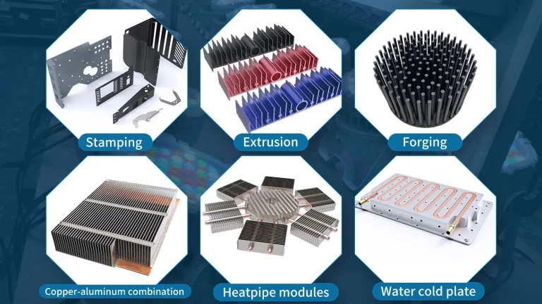
Skiving forms fins by slicing metal from a solid base and raising the cut sections. The fins remain attached to the base. Aluminum and copper can both be used, subject to the proposed geometry and manufacturing constraints. Eaton’s skiving overview explains this process and its geometry limitations.
Skiving is an option when a design needs fin density that is not practical to extrude. That is a manufacturing advantage, not proof that any skived design will outperform an extruded one. Wakefield’s skived-fin guide describes this distinction in achievable fin density.
| Review point | Skived structure | Extruded structure |
|---|---|---|
| Proposed fin geometry | Check cutting and forming feasibility | Check the available profile or die feasibility |
| Base and fins | Integral structure | Integral profile |
| Project decision | Useful when skiving resolves a geometry constraint | Worth considering when a suitable profile meets the requirements |
For your RFQ, ask the supplier to compare manufacturable options against the same footprint, operating conditions and temperature target. If a suitable profile exists, include custom extruded heat sinks in that comparison. Confirm the material, secondary machining and expected quantities before choosing the manufacturing route.
If neither option meets the thermal target within the permitted airflow and space, reassess the cooling architecture rather than continuing to add fins.
Define Heat Loss and Temperature Limits
Start with the IGBT module part number, its operating conditions and the heat that must be removed. An inverter’s output rating is not its heat load.
Account for IGBT and freewheeling-diode conduction and switching losses. For changing loads, check whether a steady-state calculation adequately represents the temperature peaks. Fuji Electric’s cooling design guidance explains these loss components and transient temperature considerations.
Keep the input information traceable. For each module, identify whether its loss estimate came from a device model, a calculation or a measurement, and record the operating point. A total loss without a module-by-module breakdown makes it harder to review the layout.
Ecotherm’s IGBT loss and junction temperature calculator can help develop an initial estimate for a two-level PWM inverter. Its steady-state result is a starting point, not a substitute for device-specific analysis and assembly testing.
In the project requirements, distinguish three items:
The module’s specified temperature limits.
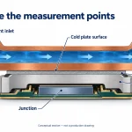
Your chosen design target and measurement location.
The expected air temperature at the heat sink inlet.
Label uncertain inputs instead of presenting them as verified values. This makes later design changes easier to understand.
Match Fin Geometry to the Installed Airflow
Closer fin spacing can add surface area while increasing resistance to airflow. Review both effects together; a higher fin count is not a complete performance specification.
The installed airflow depends on the fan and the resistance of the complete flow path. The operating point is where the fan pressure-flow curve meets the system resistance curve, as described in ebm-papst’s fan guidance. Free-air CFM does not establish the flow through a heat sink inside an enclosure.
Use the heat sink’s airflow resistance data as part of that system review. Ducts, filters, grilles and inlet or outlet restrictions also matter. Then evaluate thermal resistance at the resulting airflow—not at an unrelated catalogue condition.
Flow direction needs the same attention. Air that bypasses the fins cannot be counted as channel flow. A suitable shroud can reduce bypass, but its effect should be assessed with the rest of the installation. Vicor’s forced-convection guidance explains why channelled airflow and the full pressure-drop path matter.
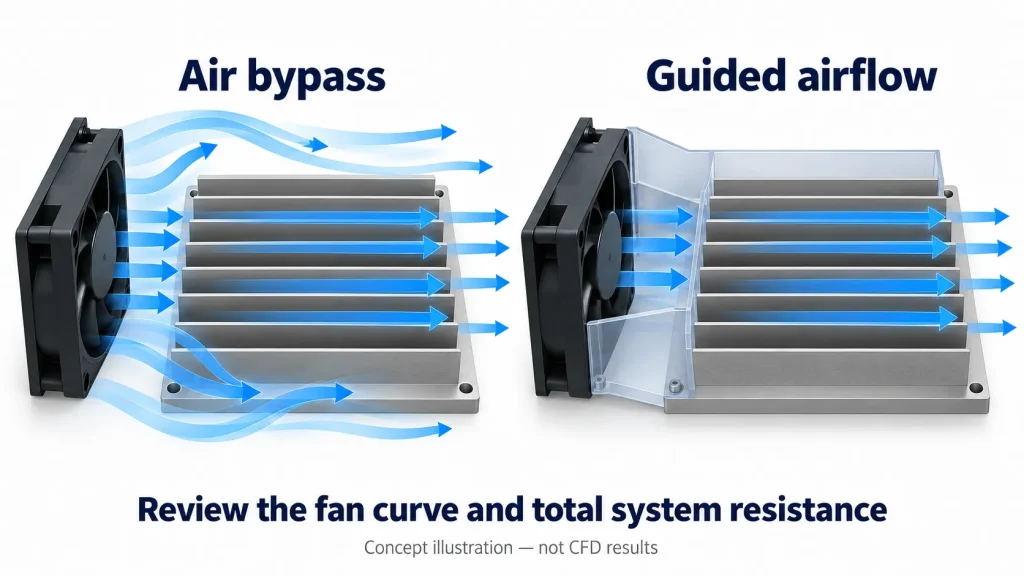
Ask for the following information when comparing proposals:
Fan model, performance curve and intended operating setting.
Airflow direction relative to the fin channels.
Enclosure or duct arrangement, including restrictions.
Conditions used for any quoted thermal resistance.
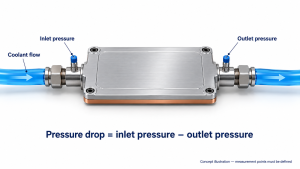
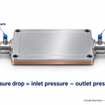
Keep airflow pressure drop separate from thermal resistance in drawings and reports. They describe different properties and use different units.
Check Module Layout, Baseplate and Mounting
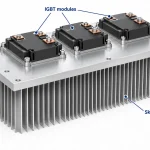
Show each module’s position and expected loss on the assembly drawing. Equal spacing should not be treated as a universal optimum. Fuji Electric recommends considering individual module losses when arranging several modules on one heat sink.
The mounting face also needs a defined specification. Use the selected module’s installation instructions for surface requirements, interface material and tightening procedure. Do not transfer a flatness limit or torque value from an unrelated module family.
For example, Semikron Danfoss’s SEMiX press-fit mounting instructions address surface condition, thermal paste application, fastening and electrical clearances for that particular assembly. Its numerical requirements should not become generic specifications for all IGBT heat sinks.
Make the drawing review practical:
Identify the module contact areas and relevant datums.
Specify flatness and surface roughness separately, with the area to be evaluated.
Show mounting-hole positions, thread depths and tool access.
Include nearby components and mechanical keep-out areas.
Mark base thickness and any geometry still open to engineering review.
Do not approve the mechanical interface from an overall length-and-width drawing alone. Ask the reviewer to identify missing mounting requirements before those details become production assumptions. Keep proposed changes on a controlled drawing revision so the thermal review and manufacturing quotation refer to the same part.
Prepare the Drawing and Validation Requirements
You do not need every thermal parameter ready before starting a discussion. Send the available information and clearly mark what still needs confirmation.
Start with:
A 2D or 3D drawing, or a dimensioned sketch.
Module part number, application and available installation space.
Sample quantity and expected production demand.
Add if available:
Module layout and estimated loss for each heat source.
Inlet air temperature, temperature targets and operating cycle.
Fan curve, airflow direction and enclosure layout.
Mounting instructions and thermal interface material.
Material, finish and inspection requirements.
For a solar inverter, storage PCS or industrial drive, name the actual assembly and operating conditions. An application label alone is not a substitute for those inputs.
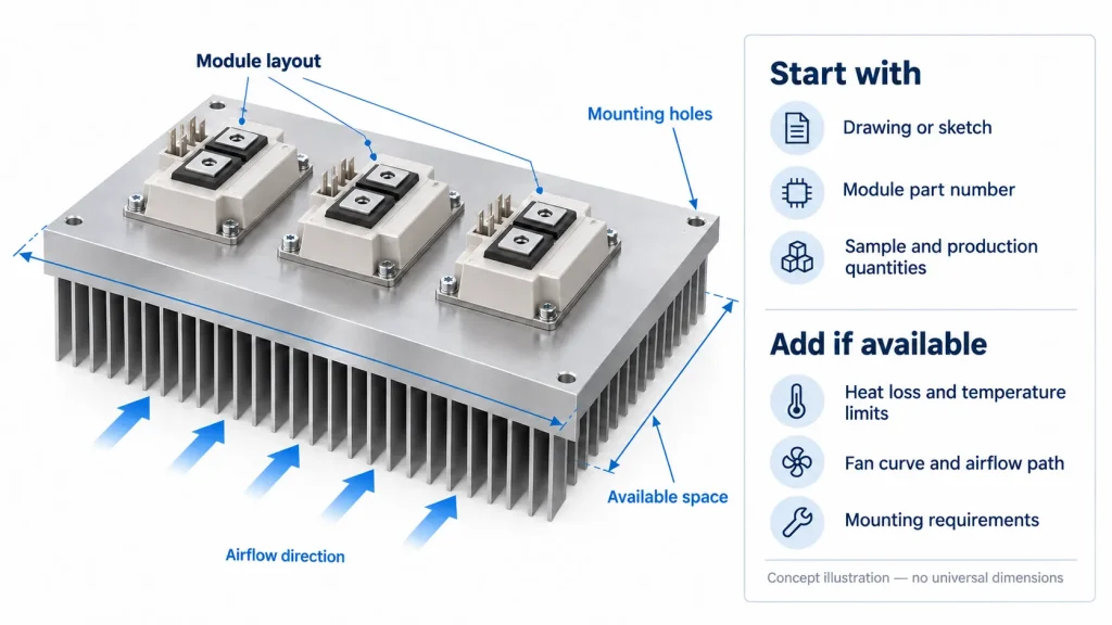
Before releasing the design for production, agree on a validation plan. Record the drawing revision, assembled configuration, heat-load assumptions, inlet conditions and measurement locations. Define the acceptance criteria and identify who will perform the evaluation and supply the results.
Keep prototype thermal validation separate from routine manufacturing inspection. Agree which checks apply to the initial assembly and which belong in the production control plan; do not assume they are identical.
To discuss manufacturing options, share your drawing and available conditions with Ecotherm through the custom skived heat sink page or email support@ecothermgroup.com. If a parameter is unknown, include the module datasheet or current assembly drawing and explain what you need to resolve.