How to Size Enclosure Vent Openings for Natural Convection Cooling
Sizing enclosure vent openings is not simply a matter of adding more holes. A passive enclosure needs enough effective inlet and outlet area, sufficient vertical separation, and a clear internal flow path to move heat by buoyancy. This guide explains a practical first-pass method for relating heat load and allowable temperature rise to vent area—while accounting for grilles, filters, component layout, and the limits of analytical estimates.
Key Takeaways
- Start with the worst-case heat load, ambient temperature, and allowable internal temperature rise—not a rule-of-thumb hole size.
- Use a low inlet and high outlet with as much practical vertical separation as the enclosure allows.
- Calculate with effective free area. Louvers, mesh, filters, perforations, and internal restrictions reduce usable area and add pressure loss.
- Inlet and outlet openings work in series. One undersized opening can limit the entire natural-convection loop.
- Larger vents normally reduce opening resistance, but benefits eventually diminish when the internal flow path or heat-transfer surfaces become the main constraint.
- Validate the assembled enclosure at maximum load and worst-case ambient conditions before relying on the result for a critical component limit.
In This Guide
1. How Natural-Convection Ventilation Works
Components inside an enclosure heat the surrounding air. As the air temperature rises, its density decreases and the warmer air tends to move upward. If the enclosure provides a low inlet and a high outlet, cooler ambient air can enter below while warmer air exits above. This buoyancy-driven circulation is commonly called the stack effect.
The driving pressure is small—often much smaller than the static pressure produced by a fan—so natural-convection performance is sensitive to restriction. Vent geometry, vertical separation, heat-source position, internal partitions, cable bundles, filters, and nearby walls can all change the resulting airflow.
Here, g is gravitational acceleration, H is the effective vertical separation between inlet and outlet, and the density difference is caused primarily by the inside-to-outside temperature difference. Greater height and temperature difference generally create more buoyancy pressure.
Convection and radiation both remove heat
Ventilation removes heat by carrying warm air out of the enclosure. At the same time, internal and external surfaces exchange heat by natural convection and thermal radiation. Surface finish, exposed wall area, heat-sink orientation, and external clearance can therefore affect total passive cooling. A vent-area estimate should not be interpreted as the only heat-transfer path.
2. Inputs Required Before Sizing Enclosure Vents
A useful natural-convection vent-area calculation begins with the operating conditions and internal layout. Collect the following information before selecting a cutout pattern.
| Input | Why it matters |
|---|---|
| Total internal heat load (W) | Defines the heat that must leave through the enclosure walls and ventilation airflow. |
| Maximum ambient temperature (°C) | Sets the inlet-air condition for the worst credible environment. |
| Allowable internal air or component temperature | Determines the available temperature rise and thermal margin. |
| Vertical separation between vent centers | Influences the buoyancy pressure available to drive airflow. |
| Nominal and free opening area | Distinguishes the panel cutout from the unobstructed flow area. |
| Grilles, louvers, mesh, filters, or labyrinths | Reduce free area and introduce additional local pressure loss. |
| Internal component layout | Controls whether air passes the heat sources or bypasses them. |
| Orientation and installation clearance | Affects plume rise, external recirculation, and whether vents are blocked after installation. |
Use worst-case temperature conditions
A design evaluated at 25°C room temperature may not be adequate at a 40°C plant ambient. Use the highest realistic ambient temperature and maximum credible dissipation. If the allowable component temperature comes from a semiconductor limit, include the device-to-case, interface, and heat-sink thermal path instead of treating internal air temperature as the component temperature.
Free area is not the same as cutout area
If a grille has a 60% free-area ratio, a 100 cm² panel cutout provides only about 60 cm² of geometric free area before its pressure-loss characteristics are considered. Fine filters can add significant resistance even when their visible area appears large. Use supplier pressure-drop data when available.
3. A Practical Vent-Area Calculation Method
A first-pass calculation can be organized into three steps: estimate the airflow needed to carry the heat, estimate the buoyancy pressure available, and determine the effective opening area needed to pass that airflow.
Step 1: Estimate the heat-carrying airflow
Q̇air is the heat carried by the ventilation air, ρ is air density, cp is specific heat, V̇ is volumetric airflow, and ΔT is the air-temperature rise. This gives a useful airflow target, but not all enclosure heat necessarily leaves in the air; walls and surfaces may also reject heat by convection and radiation.
Step 2: Estimate stack pressure
Use the enclosure’s effective vent separation and the estimated average inside-air temperature to estimate buoyancy pressure. Because the internal temperature distribution is rarely uniform, the result is an approximation.
Step 3: Relate airflow to effective opening area
Cd is a discharge coefficient representing opening losses and Aeq is the equivalent area of the complete inlet-and-outlet path. For two openings with similar loss characteristics, an engineering approximation is:
If inlet and outlet free areas are equal, the equivalent area is smaller than either individual opening because both restrictions act in series. This is why one opening should not be sized while the other is ignored.
What happens when openings are enlarged?
Increasing vent area generally reduces opening resistance and increases airflow until another part of the system becomes limiting. The improvement then shows diminishing returns because internal passages, filters, heat-transfer coefficients, or external clearance control performance. A larger vent does not inherently eliminate the buoyancy force, but it may create unnecessary ingress, structural, EMC, or safety compromises.
4. Vent Placement and the Internal Airflow Path
Vent placement converts the calculated area into useful cooling. The usual passive layout places an inlet low in the enclosure and an outlet high above the heat sources. Increasing the vertical separation strengthens the available stack pressure and encourages air to sweep through more of the enclosure.
| Placement choice | Likely effect |
|---|---|
| Low inlet and high outlet | Supports a bottom-to-top buoyancy path and greater effective stack height. |
| Inlet and outlet close together | Can create short-circuit flow that bypasses hot components. |
| Outlet below or beside the main plume | May allow hot air to collect near the top of the enclosure. |
| Blocked external clearance | Can cause discharged warm air to recirculate back into the inlet. |
| Dense wiring or horizontal plates | Adds internal resistance and may split or stop the vertical flow path. |
Keep the inlet where it can draw the coolest available air. Position the exhaust above the dominant heat sources, and leave clearance for the plume after it exits. Avoid placing both openings on the same small region unless the internal flow path has been deliberately controlled.
Protection requirements remain part of the design
Bottom vents may admit dust or moisture, while top vents may allow falling debris to enter. Louvers, labyrinths, screens, and filters can improve protection but increase resistance. Thermal performance must be balanced with ingress protection, electrical safety, EMC, acoustic, and structural requirements. A vent-area calculator does not certify compliance with those requirements.
5. Integrating an Extruded Heat Sink Inside the Enclosure
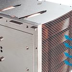
An internal heat sink and the enclosure vents form one thermal system. The heat sink transfers component heat to the internal air, and the vents help replace that warmed air with cooler ambient air. If either side is restricted, the other cannot deliver its expected performance.
- Orient straight heat-sink channels vertically when the product orientation permits.
- Leave clearance above the fins so the warm plume can rise toward the outlet.
- Avoid placing a solid cover, PCB edge, or cable bundle directly over the fin channels.
- Keep the inlet path connected to the lower part of the heat sink instead of allowing air to bypass directly to the outlet.
- Include device, interface, base-spreading, heat-sink-to-air, and enclosure-air temperature rise in the full thermal path.
Fin spacing optimized for open-air natural convection may behave differently inside a compact enclosure because local temperature, wall proximity, and the vent path change the surrounding airflow. Treat catalogue or open-bench thermal resistance as a reference condition, not a guaranteed installed value.
6. Validation and Common Sizing Mistakes
Analytical vent sizing is a useful starting point, but the assembled product should be checked under representative worst-case conditions. Use maximum internal dissipation, maximum specified ambient temperature, the normal installed orientation, and the actual grilles, filters, wiring, and covers.
| Validation check | What to confirm |
|---|---|
| Thermal soak test | Temperatures stabilize below the applicable component and material limits with suitable margin. |
| Temperature mapping | Inlet, outlet, internal air, heat-sink base, and critical component temperatures reveal hot-air stratification and hotspots. |
| Airflow visualization | Smoke or another safe visualization method confirms that air enters low, crosses the heated region, and exits high. |
| Installed-position check | Nearby panels, walls, cables, and adjacent equipment do not block or recirculate the airflow. |
| Contamination review | Expected dust loading or filter aging does not remove the required free area during service. |
Common mistakes to avoid
- Using nominal cutout area instead of effective free area.
- Sizing the outlet while ignoring a smaller or more restrictive inlet.
- Assuming all generated heat must leave in the ventilation air without checking enclosure-wall heat transfer.
- Using an average room ambient instead of the highest specified inlet-air temperature.
- Placing openings close together so air bypasses the hot components.
- Ignoring filters, perforated guards, cable bundles, internal plates, or narrow external clearances.
- Treating internal air temperature as semiconductor junction temperature.
- Relying on a calculated value without testing the final layout.
Frequently Asked Questions
What inputs are needed for a natural-convection vent-area calculation?
At minimum, define the internal heat load, maximum ambient temperature, allowable internal temperature rise, enclosure orientation, vertical separation between inlet and outlet, and the free area and resistance of any grille, filter, or screen.
How do inlet and outlet positions affect passive enclosure cooling?
A low inlet and high outlet create a longer buoyancy path. If the openings are close together or poorly connected to the hot zone, air may bypass the components and the required vent area may increase.
Should the inlet and outlet vents be the same size?
They do not have to be identical, but similar effective areas often avoid making one opening the dominant restriction. The complete inlet-and-outlet path should be calculated as openings in series.
What happens if the enclosure vent area is too small?
Opening resistance increases, buoyancy-driven airflow falls, and the internal air and component temperatures rise. The effect may be especially severe when filters or internal obstructions are added.
Can enclosure vents be too large?
Thermally, larger openings usually reduce vent resistance, but the improvement eventually becomes small when another restriction controls airflow. Excessive openings can also conflict with ingress protection, EMC, safety, strength, and contamination requirements.
Do filters and grilles change the calculation?
Yes. They reduce free area and add pressure loss. Use the manufacturer’s free-area ratio and pressure-drop data where available instead of relying only on the panel cutout dimensions.
Why is enclosure orientation important?
Natural convection relies on gravity and density differences. Rotating the enclosure can shorten the effective stack height, turn vertical heat-sink channels sideways, or place the outlet away from the warm-air plume.
How should the calculated vent size be validated?
Test the complete assembly at maximum load, worst-case ambient temperature, normal installed orientation, and with the actual covers, filters, wiring, and surrounding clearances. Measure critical component and internal-air temperatures after thermal equilibrium is reached.
Need a Heat Sink That Fits Your Passive Enclosure?
Ecotherm has 22 years of custom heat sink manufacturing experience and supports low-volume projects with an MOQ starting from one piece. Share your heat-source drawing, heat load, temperature limits, enclosure space, orientation, and vent arrangement for a free drawing feasibility review and custom heat sink solution recommendation.