High Heat Flux Cold Plate Design: Why Components Still Overheat
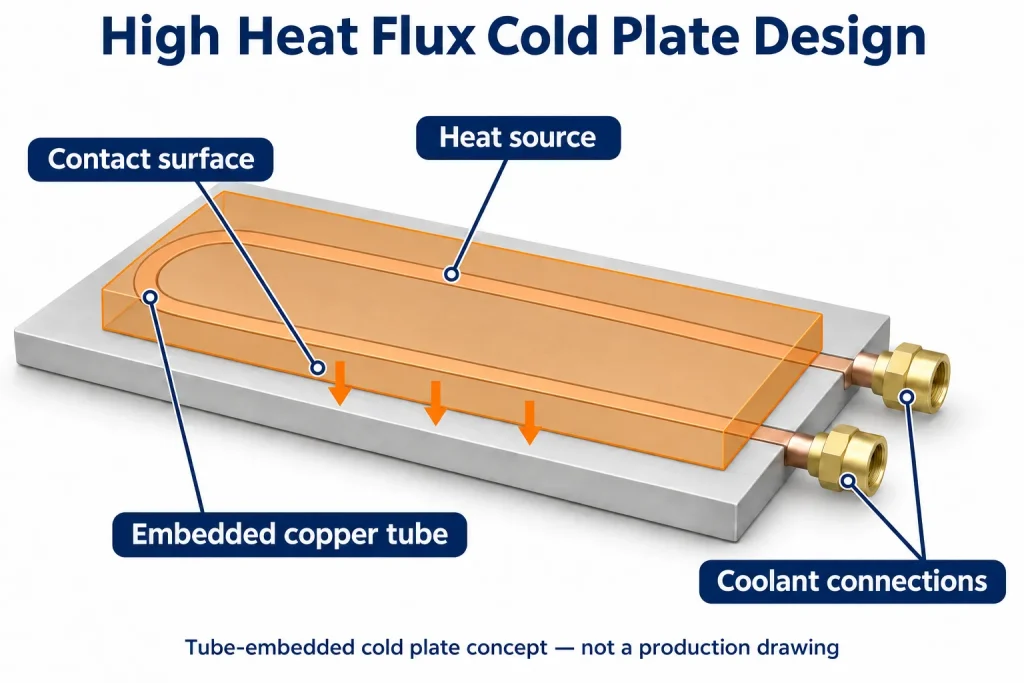
When choosing a liquid cold plate, buyers often start with one question: “How many watts can it dissipate?”
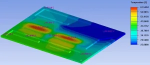
Total power is a useful starting point, but it does not tell you whether a cold plate suits your assembly. The location of the heat, the coolant flow beneath each device, and the contact between the device and the plate all affect the final temperature.
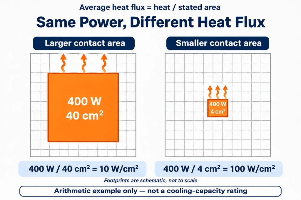
Two assemblies that each need to dissipate 400 W may therefore require different cold plate designs. High heat flux cold plate design starts with understanding where that heat is concentrated.
1. How Much Area Does the Heat Come From?
Consider two situations:
- The heat is spread across a relatively large contact area.
- The same amount of heat is concentrated in a much smaller contact area.
The second situation places more heat into each unit of area, creating a different local cooling requirement.
The heat transferred per unit area is called heat flux. When discussing a cold plate, provide more than the total heat load. Explain how large each heat source is and where it will be mounted.
A single cold plate may also cool several devices with different heat loads. A total power figure alone does not show the supplier which locations need the most cooling.
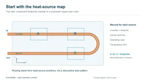
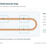
Start with a simple layout showing:
- The position and dimensions of each device.
- The heat each device needs to dissipate.
- The device with the most demanding temperature requirement.
You do not need a complete thermal simulation to begin the discussion. A clearly annotated mounting drawing can help both sides understand the requirement.
2. Does Coolant Reach the Areas That Need It Most?
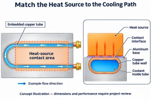
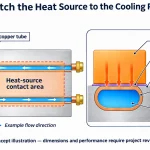
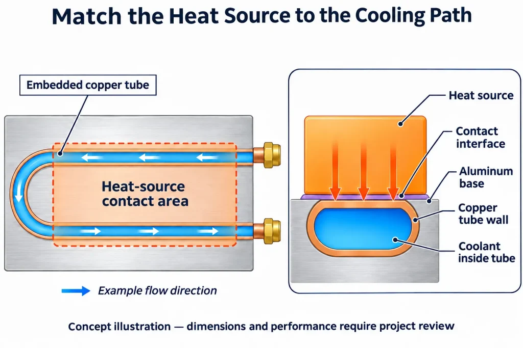
A cold plate contains internal passages called channels, through which coolant flows.
Heat must pass from the device into the plate before the coolant carries it away. Along with checking whether the plate fits the assembly, review how its internal channels relate to the device positions.
For example, a major heat source may overheat if the cooling area beneath it is unsuitable or receives insufficient coolant flow.
Adequate total system flow does not guarantee adequate cooling at every heat source.
When discussing a design with a supplier, ask:
- How are the channels arranged beneath the main heat sources?
- Can coolant flow adequately through those regions?
- Have the individual device temperatures been evaluated with the devices operating together?
If a device runs too hot, do not assume that increasing flow will solve the problem. First identify where the overheating occurs and why that region is not being cooled adequately.
3. Material Matters, but So Does Contact with the Device
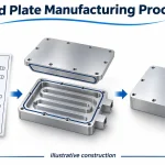
Cold plate material affects heat transfer, but the words “copper” or “aluminum” do not establish how well the complete design will perform. Material selection must also account for the plate structure, coolant, weight and cost.
Another easily overlooked issue is contact between the device and the cold plate.
Even a suitable internal design can perform poorly if heat cannot pass effectively from the device into the plate.
Check three aspects of the interface.
First, are the mating surfaces flat enough?
If the device mounting surface or the cold plate contact surface is not sufficiently flat, some areas may make contact while others leave gaps. This is a flatness issue.
Second, does the surface texture meet the requirement?
This concerns surface roughness. Flatness and roughness describe different properties. A surface that looks smooth is not necessarily flat enough across the mounting area.
Third, is the thermal interface material suitable and correctly installed?
Thermal grease, pads and other thermal interface materials—often called TIMs—help fill gaps between the device and the plate. Check more than the material itself. Review its coverage, installed thickness and whether the mounting arrangement applies pressure as required.
There is no single specification that suits every assembly. Use the requirements of the actual device and interface material.
If only one device is unexpectedly hot, check whether it is seated correctly and makes even contact before deciding to change the cold plate.
4. Do the Test Conditions Reflect Actual Coolant Conditions?
Ambient temperature also matters.
However, room temperature and the temperature of the coolant entering the cold plate are different measurements.
Cooling systems reject heat and control temperature in different ways. To judge whether a plate is suitable, establish the coolant temperature that actually reaches its inlet, rather than relying only on the room temperature.
A result obtained with a lower coolant inlet temperature, for example, does not automatically demonstrate that the same design will meet its temperature limit with warmer coolant.
Before comparing designs or arranging a test, clarify the following:
| What to confirm | Why it matters |
|---|---|
| Heat load and position of each device | Identifies the areas that need the most cooling |
| Coolant inlet temperature | Defines the coolant conditions reaching the plate |
| Flow through the individual cold plate | Total system flow alone is insufficient |
| Device mounting and interface material | Contact differences can affect the result |
| Temperature limit for each critical device | Establishes whether the design meets the requirement |
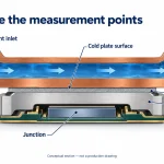
Also confirm where temperature is measured. Chip junction temperature, device case temperature and cold plate surface temperature are not interchangeable. Our guide to comparing cold plate thermal resistance and performance data explains these differences in more detail.
Ultimately, the question is specific to your assembly: can each critical device stay within its temperature limit under the intended mounting and coolant conditions?
If you are evaluating a custom liquid cold plate, send Ecotherm your mounting drawing, device locations, known heat loads and coolant conditions. Point out the location you are most concerned about. Mark missing parameters as “to be confirmed”—you do not need every detail finalized before starting the discussion.