How to Choose the Best GPU Cooler for Top Performance
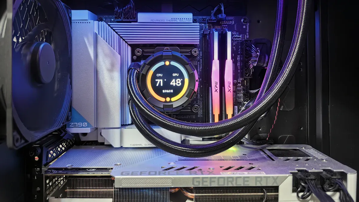
GPU Cooler Types and Thermal Design Guide
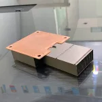
A GPU cooler transfers heat away from the graphics processor, memory, and power-delivery components so they can operate within their temperature limits. Consumer graphics cards usually use an open-air or blower-style heatsink and fan assembly. OEM graphics systems, AI accelerators, servers, and compact edge devices may require a purpose-built heat-pipe module, vapor chamber, dense fin stack, or liquid cold plate.
The right GPU cooler is not simply the largest model or the one with the most fans. Selection depends on the heat-source map, continuous and peak power, maximum component temperatures, available airflow, mechanical envelope, mounting method, acoustic target, operating environment, and production requirements.
If you are comparing standard cooling architectures, the sections below explain the main options. If you are developing a non-standard GPU board or system, a custom GPU heatsink should be designed around the complete thermal and mechanical specification rather than a consumer cooler model.
What Is a GPU Cooler?
A GPU cooler is the thermal assembly that conducts heat away from the heat-generating components on a graphics board and rejects that heat into air or liquid. A complete assembly may include:
- A copper or aluminum contact base
- Thermal interface material between components and the cooler
- Heat pipes or a vapor chamber for heat transport and spreading
- Aluminum or copper fins for increased surface area
- Axial fans or a blower for forced airflow
- A cold plate, fittings, and coolant channels for liquid cooling
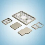
- Mounting hardware, springs, backplates, frames, and structural supports
The GPU die is not the only heat source. Graphics memory and voltage-regulation components can also require direct contact with thermal pads, secondary plates, or extended sections of the main cooler. A design that lowers the GPU die temperature but leaves memory or power components inadequately cooled is not a complete thermal solution.
The basic air-cooling path is:
GPU / memory / VRM -> thermal interface -> base or spreader -> heat pipes or fins -> airflow -> system exhaust
For direct liquid cooling, the path becomes:
GPU / memory / VRM -> thermal interface -> cold plate -> coolant -> facility or system heat exchanger
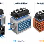
Main Types of GPU Coolers
| GPU cooler type | How it works | Best suited to | Main design considerations |
|---|---|---|---|
| Open-air cooler | Axial fans move air through a fin stack and discharge it into the enclosure | Consumer graphics cards and well-ventilated workstations | Case airflow, recirculation, card spacing, fin resistance, and acoustics |
| Blower-style cooler | A centrifugal blower forces air through a ducted fin stack, often toward an external vent | Systems that need controlled airflow direction or closely spaced cards | Pressure capability, duct leakage, noise, inlet restriction, and exhaust path |
| Passive heatsink | Natural convection and radiation remove heat without a dedicated fan | Low-power or noise-sensitive systems with sufficient surface area | Orientation, chimney effect, ambient temperature, surface area, and enclosure ventilation |
| Heat-pipe module | Heat pipes transport heat from a compact base to a larger or remote fin stack | Space-constrained systems and designs with separated heat source and rejection area | Heat-pipe layout, orientation, bending, wick limits, base contact, and fin integration |
| Vapor-chamber cooler | A planar two-phase spreader distributes heat across a wider base before rejection through fins or heat pipes | Concentrated heat sources, thin assemblies, and designs requiring improved spreading | Chamber size, heat-source location, support structure, flatness, and mechanical loading |
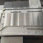
| Liquid cold plate | Coolant flows through channels close to the heat sources and carries heat out of the local enclosure | High sustained heat loads, dense servers, AI accelerators, and low-airflow environments | Coolant, flow rate, pressure drop, channel design, sealing, corrosion, cleanliness, and leak validation |
Open-Air GPU Cooler
An open-air GPU cooler normally combines one or more axial fans with a heat sink, heat pipes, and a base plate. The fans draw air from inside the enclosure and push it through the fins. Because the warm air is released back into the system, enclosure intake and exhaust design remain part of the GPU cooling solution.
This architecture can provide a good balance of thermal performance, noise, cost, and serviceability when card spacing and case ventilation are sufficient. Adding more fans does not automatically improve cooling: the fin geometry, airflow path, recirculation, fan operating point, and contact quality can be more important than fan count.
Blower-Style GPU Cooler
A blower-style cooler uses a centrifugal fan and a more controlled air channel. This can help direct heated air through a defined outlet rather than releasing it around the board. The tradeoff is that a compact blower may need to operate at higher speed to overcome the resistance of the duct and fin stack.
Blower designs should be evaluated as a pressure-flow system. A fan's free-air flow rating does not represent the flow that will pass through a restrictive heat sink, grille, filter, and chassis. The actual operating point is determined by the intersection of the fan curve and the system-resistance curve.
Passive GPU Heatsink
A passive GPU heatsink has no dedicated fan. It depends on conduction into a large heat-dissipating surface and natural air movement around the fins. This approach eliminates fan noise and a mechanical wear component, but it is practical only when the total heat load, available volume, orientation, and enclosure ventilation support the required thermal resistance.
For a fanless design, orientation and air-channel geometry should be defined early. A passive heat sink tested in open air may perform differently after it is installed inside a compact or sealed enclosure.
Heat-Pipe GPU Cooling Module
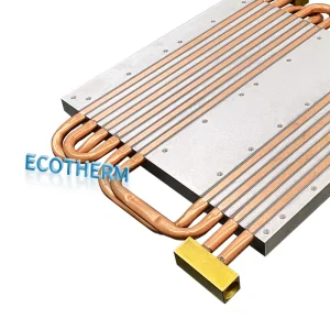
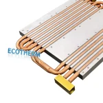
Heat pipes transport heat by evaporation and condensation of an internal working fluid. They can move heat from the GPU base to a fin stack located where more space or airflow is available. This makes a heat-pipe cooling module useful when the heat source and the best heat-rejection area are not in the same location.
Heat-pipe diameter, length, flattening, bend radius, orientation, wick structure, heat input, and condenser design all affect performance. The pipe layout also has to fit around board components and maintain reliable contact with the base and fins.
Vapor-Chamber GPU Cooler
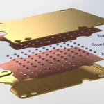
A vapor chamber is a flat, sealed two-phase heat spreader. It is often placed beneath a fin stack or combined with heat pipes to distribute heat from a concentrated GPU package across a larger area. This can reduce localized spreading resistance where a solid plate would create an excessive temperature gradient.
A custom vapor chamber heat sink must be designed with the heat-source location, chamber envelope, internal support, mounting load, surface flatness, and integration method in mind. A vapor chamber improves heat spreading, but it still needs an effective path to reject the heat into air or liquid.
Liquid Cold Plate and GPU Liquid Cooling
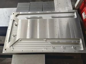
A liquid cold plate places coolant channels close to the heat sources. It moves heat to a remote radiator, coolant distribution unit, or facility-water loop. This can be valuable when air cooling cannot meet the thermal target within the available volume or acoustic limit.
Liquid cooling is a system-level decision rather than a drop-in guarantee of better performance. The plate, pump, hoses or manifolds, fittings, heat exchanger, coolant, controls, and service strategy must work together. Channel design must balance heat transfer with allowable pressure drop, while materials and joints must be selected for corrosion resistance, cleanliness, sealing, and production repeatability.
Ecotherm's custom liquid cold plate and GPU liquid cooling solutions pages provide more detail for direct-to-chip and server applications.
GPU Cooler vs. CPU Cooler
GPU and CPU coolers may use similar thermal technologies, but they are not automatically interchangeable.
A CPU cooler is normally designed around a defined processor socket, integrated heat spreader, keep-out zone, and mounting system. A GPU cooler must match a specific board layout and may need to contact the exposed GPU package, memory devices, and VRM components at different heights. It must also account for card thickness, PCIe spacing, backplate loading, board deflection, and the direction of airflow through the chassis.
Using a CPU cooler on a GPU without a purpose-designed mounting and component-cooling plan can leave memory or power components without adequate contact. It can also introduce mechanical stress or interference. For an OEM design, cooler compatibility should be established from the PCB, component stack-up, mechanical model, and thermal map.
How to Choose a GPU Cooler
Define the Application First
Start with the operating context, not a cooler catalog.
- Is this a consumer graphics card, workstation, AI accelerator, embedded computer, or server?
- Will the GPU run intermittently or at a sustained high load?
- Is the board installed alone, in a multi-card system, or in a dense rack?
- Is cooling air clean and unrestricted, filtered, recirculated, or shared with other hot components?
- Are noise, weight, height, service access, or liquid availability major constraints?
The same GPU can require a different thermal solution in an open workstation, a compact edge device, and a dense server.
Calculate the Thermal Requirement
An initial thermal-resistance target can be estimated from the allowable temperature rise and heat load:
Required total thermal resistance <= (maximum component temperature - local ambient or coolant temperature) / heat load
This is only a starting point. The total path includes interface resistance, contact resistance, base spreading, heat-pipe or chamber transport, fin-to-air or channel-to-coolant resistance, and system-level recirculation. Peak power and transient behavior may also need to be evaluated separately from the continuous operating condition.
Map Every Heat Source
Do not treat the board as a single uniform heat source. Identify:
- GPU package location and contact area
- Memory locations and allowable temperatures
- VRM and power-stage losses
- Other nearby components affected by cooler coverage
- Heat-source heights and tolerance stack-up
- Components that cannot carry mechanical load
This map determines whether the design needs a common base, separate contact pedestals, thermal pads, a frame, a backplate, or multiple cooling zones.
Check Airflow and System Resistance
For air cooling, define both airflow and pressure. Fin pitch, fin length, card spacing, filters, grilles, ducts, cables, and neighboring boards all add resistance. A dense fin stack may offer more surface area but perform poorly if the available fan cannot move sufficient air through it.
Air should enter the fin field, pass through the heated surfaces, and leave the enclosure without excessive recirculation. In a multi-GPU system, the temperature and flow reaching downstream cards may be different from the inlet condition.
Confirm Space, Mounting, and Contact
The mechanical envelope must include more than overall length, width, and height. Confirm:
- Mounting-hole positions and fastener access
- Maximum card thickness and adjacent-slot clearance
- Base flatness and component-height tolerances
- Thermal-pad thickness and compression range
- Spring load or mounting pressure
- PCB bending and cooler mass
- Shock, vibration, shipping, and installation orientation
- Connector, cable, and service clearances
Thermal performance depends on repeatable contact. A high-performance heat sink cannot compensate for an uncontrolled interface gap or uneven mounting pressure.
Plan for Reliability and Manufacturing
The best prototype concept is not necessarily the best production design. Process selection should consider material, geometry, tooling, tolerance, annual volume, inspection, assembly, service life, and cost.
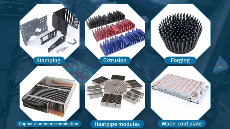
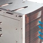
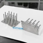
For example, CNC machining offers flexibility for early samples and complex bases. Extrusion can be economical for suitable constant cross-sections. A custom skived heat sink can create dense, thin fins from a single material block. Zippered or bonded fin structures can support larger fin areas, while heat pipes and vapor chambers add two-phase heat transport when solid conduction is insufficient.
When Do You Need a Custom GPU Cooler?
A custom GPU cooler is appropriate when a standard assembly cannot meet one or more core requirements:
- The PCB layout or mounting pattern is non-standard.
- GPU, memory, and VRM components require coordinated contact cooling.
- The system has a strict height, weight, or card-spacing limit.
- Heat must be transported to a remote fin stack or chassis wall.
- Sustained workload creates a different requirement from a short consumer workload.
- Fan noise or available airflow limits conventional air cooling.
- Multiple accelerators share a restricted airflow path.
- A vapor chamber or heat-pipe layout must match the heat-source map.
- The product requires direct liquid cooling or manifold integration.
- The cooler must be optimized for repeatable assembly and volume manufacturing.
For high-density compute platforms, see Ecotherm's HPC cooling solutions for additional air- and liquid-cooling considerations.
Choosing the Right Custom GPU Cooling Technology
| Project condition | Possible starting technology | Why it may fit | What must be validated |
|---|---|---|---|
| Moderate load and adequate airflow | Extruded or machined aluminum heatsink with fan | Simple architecture and established production methods | Thermal resistance, airflow, base spreading, noise, and mounting |
| Concentrated source and limited base thickness | Vapor chamber with fin stack | Spreads heat across a larger rejection area | Chamber envelope, support, flatness, source position, and integration |
| Heat must move to a remote location | Heat-pipe module | Connects a compact source area to a better airflow or fin location | Pipe capacity, orientation, bends, contact, and condenser design |
| High fin density is required | Skived or assembled-fin heatsink | Increases surface area within a defined volume | Fin resistance, fan pressure, manufacturability, cleaning, and handling |
| Air cooling cannot meet the system target | Liquid cold plate | Moves heat to a remote liquid loop | Flow, pressure drop, sealing, corrosion, coolant, controls, and service |
Final technology selection should follow a review of the thermal map, mechanical model, airflow or coolant conditions, reliability target, and production plan.
Custom GPU Cooler Development Process
A practical development process connects thermal performance with mechanical fit and manufacturing feasibility:
- Requirements review 鈥?Confirm heat loads, component limits, ambient or coolant conditions, airflow, space, mounting, reliability, quantity, and cost targets.
- Cooling concept 鈥?Compare air-cooled, heat-pipe, vapor-chamber, and liquid approaches.
- Thermal and mechanical design 鈥?Define contact areas, heat-spreading path, fins or channels, interfaces, mounting, and structural support.
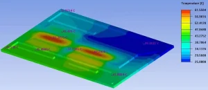
- Simulation and design review 鈥?Evaluate temperature distribution, airflow or coolant flow, pressure drop, and key design sensitivities where project data supports modeling.
- Design for manufacturing 鈥?Select materials, processes, tolerances, joints, finishes, inspection methods, and assembly steps.
- Prototype and validation 鈥?Build samples and test fit, contact, temperature, pressure drop, acoustics, leakage where applicable, and operating reliability.
- Production release 鈥?Finalize controlled drawings, inspection criteria, process parameters, and repeatable assembly requirements.
Information to Send for an Engineering Review
The following information helps a thermal supplier evaluate feasibility without guessing:
- 2D drawing and 3D CAD file, preferably STEP or IGES
- PCB outline, component locations, and keep-out zones
- GPU, memory, VRM, and other heat loads
- Continuous, peak, and transient operating conditions
- Maximum component or case temperatures
- Local ambient-air or coolant-inlet temperature
- Available airflow, fan curve, or coolant-flow conditions
- Maximum pressure drop where applicable
- Cooler envelope, weight, and slot limits
- Mounting holes, contact heights, tolerances, and preferred TIM
- Operating orientation and environmental requirements
- Prototype quantity, annual volume, and project schedule
If some inputs are not yet fixed, send the available drawing and operating assumptions. The missing items can be identified during the initial review.
FAQ
What type of GPU cooler is best?
There is no single best GPU cooler for every system. An open-air cooler can be suitable for a well-ventilated workstation, while a blower may be useful when exhaust direction must be controlled. Heat pipes and vapor chambers help when heat must be transported or spread within a limited space. Liquid cooling may be appropriate for high sustained loads or dense systems, provided the complete coolant loop is engineered and validated.
Do more GPU fans always improve cooling?
No. Fan count alone does not determine performance. Cooling depends on the fan curve, fin resistance, airflow path, heat spreading, interface quality, recirculation, and enclosure exhaust. More fans can add airflow, but they can also add noise, power consumption, and packaging complexity.
Can a CPU cooler be used on a GPU?
Only with a mounting system and thermal plan designed for the specific board. A GPU board may require cooling for memory and power components in addition to the main processor. A CPU cooler does not automatically provide the required coverage, mechanical support, or clearances.
Is liquid GPU cooling always better than air cooling?
Not automatically. Liquid cooling can move high heat loads to a remote heat exchanger, but it adds pumps, channels, fittings, controls, pressure-drop limits, sealing requirements, and service considerations. A well-designed air cooler may be the more reliable and economical choice when space and airflow are available.
What can be customized in a GPU cooling module?
The contact base, heat pipes, vapor chamber, fin geometry, materials, fans, ducting, cold-plate channels, mounting system, backplate, interfaces, connectors, surface treatment, and assembly method can all be reviewed against project requirements and manufacturing feasibility.
What files are needed to request a custom GPU cooler?
Start with a 2D drawing or 3D model, the heat-source locations and power, temperature limits, available airflow or coolant conditions, mechanical envelope, mounting details, quantity, and application. A STEP or IGES file is useful for mechanical review.
Request a Custom GPU Cooling Review
Developing an OEM graphics board, AI accelerator, server, workstation, or edge-computing system?
Send Ecotherm your 2D or 3D drawings, heat-source map, continuous and peak power, temperature limits, airflow or coolant conditions, mechanical envelope, mounting requirements, prototype quantity, and expected production volume.
Our engineering team can review the available information, identify missing design inputs, and discuss a manufacturable GPU cooling approach using an air-cooled heatsink, heat-pipe module, vapor chamber, dense fin structure, or liquid cold plate.
Email: support@ecothermgroup.com
Recommended CTA button: Upload CAD & Thermal Requirements