What is an Optical Module? The Ultimate Guide to Principles, Types, and Troubleshooting
Working Principle of Optical Modules
Optical Modules (also known as Optical Transceivers) are critical components in fiber optic communication systems. As the core optoelectronic devices operating at the Physical Layer of the OSI model, their primary function is to perform electro-optical and photo-electric conversion during signal transmission.
An optical module is mainly composed of optoelectronic devices (including the optical transmitter and optical receiver), functional circuitry, and optical interfaces. Its fundamental role is to bridge the gap between electrical equipment and optical fibers.
As illustrated in the Optical Module Working Principle Diagram, the process functions as follows:
Transmission (Tx): An electrical signal with a specific bit rate enters the transmitting interface. It is processed by an internal driver chip, which drives a semiconductor Laser Diode (LD) or Light Emitting Diode (LED) to emit a modulated optical signal at the corresponding rate.
Reception (Rx): After transmitting through the optical fiber, the optical signal reaches the receiving interface. A photodetector diode converts the light signal back into an electrical signal. This signal is then passed through a preamplifier and output as an electrical signal at the corresponding bit rate.
External Structure of the Optical Module
Optical modules come in various types, and their external structures are not exactly the same. However, their basic compositional structure includes the following parts, as shown in Figure 1-2, which illustrates the external structure of an optical module (using the SFP package as an example).
What are the key performance indicators of optical modules?
How to Measure Optical Module Performance Indicators?
We can understand the performance indicators of an optical module from the following aspects.
💡 Optical Module Transmission
– Average Transmitted Optical Power
The average transmitted optical power refers to the optical power output by the light source at the transmitter of the optical module under normal working conditions, which can be understood as the intensity of the light. The transmitted optical power is related to the proportion of “1”s in the transmitted data signal; the more “1”s, the greater the optical power. When the transmitter sends a pseudo-random sequence signal, “1”s and “0”s are approximately equal (each accounting for half). The power tested at this time is the average transmitted optical power, measured in W, mW, or dBm. W or mW are linear units, while dBm is a logarithmic unit. In communications, we typically use dBm to express optical power.
– Extinction Ratio (ER)
The extinction ratio is the minimum value of the ratio between the average optical power when the laser is transmitting an all-“1” code and the average optical power when transmitting an all-“0” code under full modulation conditions, measured in dB. As shown in Figure 1-3, when converting an electrical signal into an optical signal, the laser in the transmitter section of the optical module converts it according to the bit rate of the input electrical signal. The average optical power for the all-“1” code represents the average power of the light being emitted by the laser, and the average optical power for the all-“0” code represents the average power when the laser is not emitting light. The extinction ratio characterizes the ability to distinguish between the 0 and 1 signals, and thus can be viewed as a measure of the laser’s operating efficiency. The typical minimum range for the extinction ratio is 8.2 dB to 10 dB.
– Center Wavelength of the Optical Signal
This is the wavelength corresponding to the midpoint of the line segment connecting the 50% maximum amplitude value in the emission spectrum. Different types of lasers, or two lasers of the same type, will have differences in center wavelength due to factors like manufacturing process and production. Even the same laser may have different center wavelengths under different conditions. Generally, optical component and optical module manufacturers provide a parameter to the user, the center wavelength 850nm, which is typically a range.
Currently, the most commonly used center wavelengths for optical modules fall into three main bands: the 850 nm band, the 1310 nm band, and the 1550nm band. Why are these three bands defined? This is related to the fiber attenuation (loss) of the optical signal’s transmission medium. Through continuous research and experimentation, it was found that fiber loss generally decreases as the wavelength increases: loss is lower at 850 nm, then increases again between 900nm and 1300 nm. It decreases again at 1310nm, reaches the minimum at 1550 nm, and tends to increase again above 1650 nm. Therefore, 850nm is the so-called short-wavelength window, and 1310 nm and 1550nm are the long-wavelength windows.
Optical Module Receiver
– Overload Optical Power
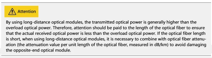
Also known as the Saturation Optical Power, this is the maximum input average optical power that the receiving component of the optical module can tolerate under a certain Bit Error Rate BER = 10-12. The unit is dBm. It is important to note that the photodetector can experience photocurrent saturation when exposed to strong light. When this occurs, the detector requires a certain amount of time to recover, during which the receive sensitivity decreases, and the received signal may be misinterpreted, leading to bit errors. Simply put, if the input optical power exceeds this overload optical power, it may damage the equipment. Strong light exposure should be avoided during operation to prevent exceeding the overload optical power.
– Receive Sensitivity
Receive sensitivity is the minimum average input optical power that the receiving component of the optical module can receive under a certain Bit Error Rate BER = 10-12. If the transmitted optical power refers to the light intensity at the transmitting end, then the receive sensitivity refers to the light intensity that the optical module can detect. The unit is dBm. Generally, the higher the data rate, the worse the receive sensitivity, the greater the minimum receiving optical power), and the higher the requirements for the receiver component of the optical module.
– Received Optical Power
The received optical power is the range of average optical power that the receiving component of the optical module can accept under a certain Bit Error Rate BER = 10-12. The unit is dBm. The upper limit of the received optical power is the overload optical power, and the lower limit is the maximum value of the receive sensitivity. Overall, if the received optical power is less than the receive sensitivity, the signal may not be received properly because the optical power is too weak. If the received optical power is greater than the overload optical power, the signal may also not be received properly due to the occurrence of bit errors.
Comprehensive Performance Indicators
– Interface Rate
This is the maximum electrical signal rate that the optical component can carry without errors. Ethernet standards specify rates such as 125Mbit/s、1.25Gbit/s、10.3125Gbit/s、41.25Gbit/s.
– Transmission Distance
The transmission distance of an optical module is primarily limited by two factors: loss and dispersion.
Loss is the energy depletion of light as it travels through the optical fiber due to absorption, scattering, and leakage of the medium. This energy is dissipated at a certain rate as the transmission distance increases.
Dispersion occurs mainly because different wavelengths of electromagnetic waves travel at different speeds in the same medium. This causes the different wavelength components of the optical signal to arrive at the receiver at different times due to the accumulated transmission distance, leading to pulse broadening and making it impossible to distinguish the signal values.
In terms of optical module performance, the distance limited by dispersion is often much greater than the distance limited by loss and can typically be disregarded. The loss limit can be estimated using the formula:
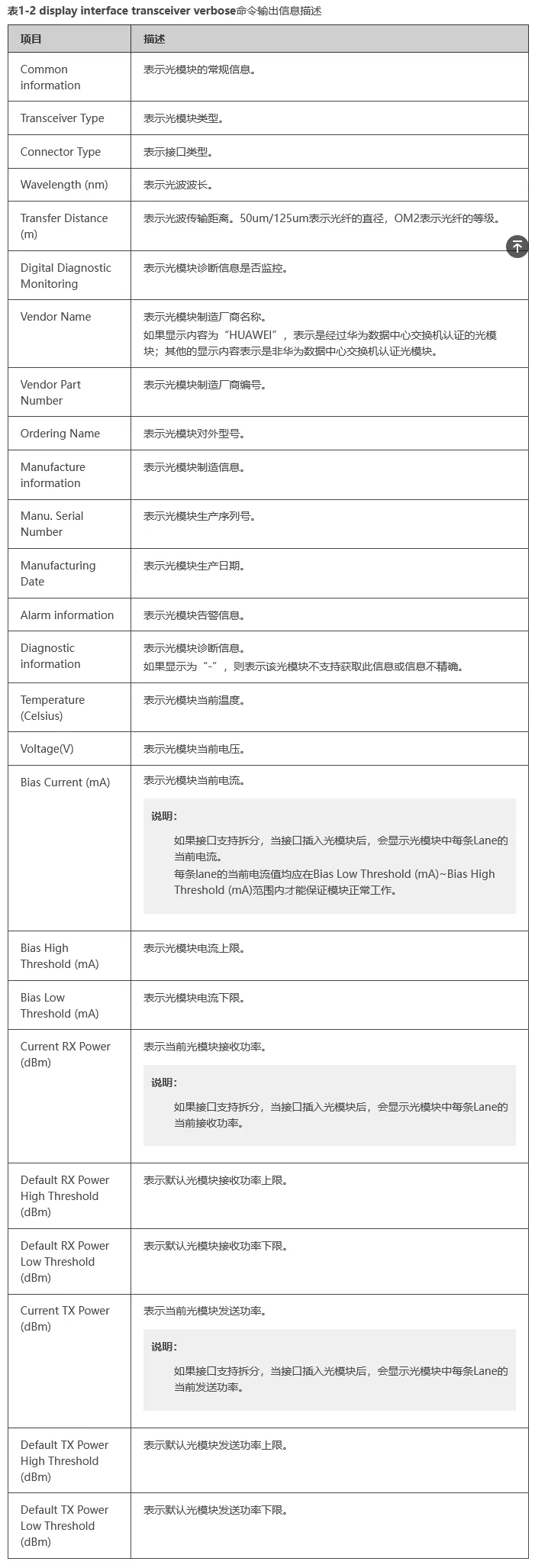
The fiber attenuation value is strongly related to the actual fiber type selected. CloudEngine series switches can use the display interface transceiver verbose command to view the general, manufacturing, alarm, and diagnostic information of the optical module on a specified interface, as shown in the table describing the output information of the display interface transceiver verbose command.
Common Types of Optical Modules
Classified by Transmission Rate
To meet the demands of various transmission rates, optical modules of different speeds have been developed, including: 400GE, 100GE, 40GE, 25GE, 10GE, GE, and FE optical modules.
Classified by Mode
Optical fibers are divided into single-mode fibers and multi-mode fibers. To accommodate these different fiber types, single-mode optical modules and multi-mode optical modules were developed.
Single-mode Optical Modules
Generally operate at a central wavelength of 1310nm or 1550nm and are designed to work with single-mode fibers.
Single-mode fibers offer wide transmission bandwidth and large capacity, making them suitable for long-distance transmission.
Multi-mode Optical Modules
Generally operate at a central wavelength of 850nm and are designed to work with multi-mode fibers.
Multi-mode fibers suffer from modal dispersion, resulting in lower transmission performance compared to single-mode fibers. However, due to their lower cost, they are suitable for lower capacity, short-distance transmission.
Classified by Center Wavelength
The operating wavelength of an optical module spans a specific range. For descriptive convenience, the parameter center wavelength is used, measured in nanometers (nm).
To support optical signal transmission across different optical bands, optical modules with various center wavelengths have been developed, such as 850nm, 1310nm, and 1550nm modules.
Classified by Color
The primary distinction between “colored” optical modules and other types lies in their center wavelengths:
Gray Light (Black-and-White): Standard optical modules typically operate at center wavelengths of 850nm, 1310nm, and 1550nm. Since their center wavelengths are singular, this type of light is referred to as “black-and-white light” or “gray light” (commonly known as Grey Optics in the industry).
Colored Light: “Colored” optical modules carry light with several distinct center wavelengths. Since these wavelengths collectively cover a spectrum, this type of light is referred to as “colored light” (WDM Optics).
Colored optical modules are categorized into two types:
CWDM (Coarse Wavelength Division Multiplexing)
DWDM (Dense Wavelength Division Multiplexing)
Within the same frequency band, DWDM modules offer a greater variety of wavelengths, allowing for more efficient utilization of spectral resources.
How it works: Light with different center wavelengths can be transmitted through a single optical fiber without interference.
A passive multiplexer (Mux) combines light from multiple colored optical modules (with different wavelengths) into a single channel for transmission.
At the remote end, a demultiplexer (Demux) separates the light back into multiple paths based on their different center wavelengths.
This process effectively saves fiber optic cabling resources. Consequently, colored optical modules are primarily used in long-distance transmission lines.
How to Decipher Optical Module Naming
Understanding optical module naming conventions allows you to fully interpret all the information contained within a manufacturer’s product name. This section uses general naming rules to provide a detailed breakdown.
Primary Causes of Optical Module Failure and Protective Measures
The main causes of optical module failure are performance degradation due to ESD (Electrostatic Discharge) damage, and optical link disconnection caused by contamination or damage to the optical port.
The main reasons for optical port contamination and damage include:
The optical port of the module is exposed to the environment, allowing dust entry and contamination.
The end face of the optical fiber connector used is already contaminated, causing secondary contamination to the module’s optical port.
Improper use of the ferrule end face of the pigtail connector, such as scratches on the end face.
Use of low-quality/inferior optical fiber connectors.
Effective protection against optical module failure is primarily divided into two types: ESD protection and physical protection.
ESD Protection
ESD damage is a major problem that causes optical device performance degradation or even the loss of the device’s optoelectronic function. Furthermore, ESD-damaged optical devices are difficult to test and screen, making failure localization difficult if they malfunction.
Handling Procedures
During transportation and transfer before use, the optical module must remain inside its anti-static packaging; it must not be arbitrarily removed or placed casually.
2. Before touching the optical module, it is necessary to wear anti-static gloves and anti-static wristbands. When installing the optical components (including the optical module), anti-static measures must also be taken.
3. The testing equipment or application device must have a good grounding wire.
It is strictly prohibited to remove the optical module from its anti-static packaging and stack it haphazardly without any protection just for installation convenience—treating it like discarded junk.
Physical Protection
The internal laser and Temperature Control Circuit (TEC) of the optical module are relatively fragile and can be easily fractured or detached upon impact. Therefore, physical protection must be maintained during both transportation and use.
Contaminants on the optical port should only be wiped gently with a cleaning swab. Non-dedicated cleaning swabs may damage the optical port, and using excessive force might cause metal parts within the swab to scratch the ceramic end face.
The design for inserting and extracting the optical module simulates manual human operation, and the push and pull forces are designed accordingly. Therefore, tools or instruments must not be used during installation and removal.
Handling Procedures
Handle the optical module gently during application to prevent dropping.
When inserting the optical module, push it in by hand; do not use any other metal tools. When extracting, first open the pull tab to the unlocked position, and then pull the tab; do not use any other metal tools.
3.When cleaning the optical port, a dedicated cleaning swab must be used; no other metal objects should be inserted into the optical port.
What should be done if the optical modules connecting between the data center switches fail to establish a connection?
Background Information
Theoretically, optical modules with the same interface standard type should be able to connect; however, in practical applications, attention must be paid to the transmit and receive optical power range and the transmission distance.
The major factors affecting optical module interoperability are shown in the table below.
| Structure | Description |
| 1. Dust Cap | Protects fiber connectors, fiber adapters, optical interfaces of optical modules, and ports of other devices from external environmental contamination and physical damage. |
| 2. EMI Fingers (Skirt) | Used to ensure a good grounding connection between the optical module and the device’s optical port. This is only present on SFP-packaged optical modules. |
| 3. Label | Used to identify the key parameters of the optical module and manufacturer information, etc. |
| 4. Connector (Gold Finger) | Used for the connection between the optical module and the board (PCB) to transmit signals and supply power to the optical module, etc. |
| 5. Housing (Shell) | Protects internal components. There are mainly two types: 1×9 housing and SFP housing. |
| 6. Receive Interface (Rx) | Fiber optic receiving interface. |
| 7. Transmit Interface (Tx) | Fiber optic transmitting interface. |
| 8. Bale Clasp (Latch/Handle) | Used for plugging and unplugging the optical module. For ease of identification, the color of the clasp varies according to the different wavelengths supported. |
Symptom
Two optical interfaces are connected via optical fiber, but the local port is Down, indicating a failure in optical module interoperability.
Possible Causes
The optical module used is not certified for Huawei Data Center switches.
Optical module and fiber mismatch.
The port is shut down (
shutdown).Transmit optical power is too low or too high.
Receive optical power is too low or too high.
Optical modules on both ends are mismatched (in compatibility/type).
Troubleshooting Steps
Confirm whether the optical module on the Down port is certified by Huawei Data Center switches. CE series switches must use Huawei Data Center switch certified optical modules; the reliability of uncertified optical modules cannot be guaranteed, which may prevent the port from going UP.
Check if the optical module and the optical fiber are matched:
Single-mode optical modules (typical wavelengths: 1310nm, 1550nm) correspond to single-mode fiber (typically yellow).
Multi-mode optical modules (typical wavelength: 850nm) correspond to multi-mode fiber (typically orange).
Execute the command
display interface transceiverto check for any alarm information under “Alarm information” for the optical module.
display interface 10ge 1/0/1 transceiver
10GE1/0/1transceiver information:-------------------------------------------------------------------Commoninformation:TransceiverType :10GBASE_SRConnectorType :LCWavelength(nm) :850TransferDistance (m) :30(62.5um/125um OM1)80(50um/125umOM2)300(50um/125umOM3)400(50um/125umOM4)DigitalDiagnostic Monitoring :YESVendorName :HUAWEIVendorPart Number :02318169OrderingName :-------------------------------------------------------------------Manufactureinformation:Manu.Serial Number :AQG269YManufacturingDate :2013-10-20VendorName :HUAWEI-------------------------------------------------------------------Alarminformation:-------------------------------------------------------------------
If a LOS Alarm (Loss of Signal) occurs, it indicates that the peer end is not sending a signal. In interface mode, execute the command display this to check whether the ports on both ends are shutdown. If a port is shut down, execute the undo shutdown command.
4. Execute the command display interface transceiver verbose to check the optical module’s diagnostic information and look for any alarm information regarding transmit or receive optical power.
display interface 10ge 1/0/1 transceiver verbose
10GE1/0/1transceiver information:-------------------------------------------------------------------Commoninformation:TransceiverType :10GBASE_SRConnectorType :LCWavelength(nm) :850TransferDistance (m) :30(62.5um/125um OM1)80(50um/125umOM2)300(50um/125umOM3)400(50um/125umOM4)DigitalDiagnostic Monitoring :YESVendorName :HUAWEIVendorPart Number :02318169OrderingName :-------------------------------------------------------------------Manufactureinformation:Manu.Serial Number :AQG269YManufacturingDate :2013-10-20VendorName :HUAWEI-------------------------------------------------------------------Alarminformation:-------------------------------------------------------------------Diagnosticinformation:Temperature(Celsius) :33.68Voltage(V) :3.29BiasCurrent (mA) :7.97BiasHigh Threshold (mA) :13.20BiasLow Threshold (mA) :4.00CurrentRX Power (dBm) :-2.15DefaultRX Power High Threshold (dBm) :1.00DefaultRX Power Low Threshold (dBm) :-11.90CurrentTX Power (dBm) :-2.07DefaultTX Power High Threshold (dBm) :1.00DefaultTX Power Low Threshold (dBm) :-9.30-------------------------------------------------------------------
This is the final section of the troubleshooting guide. Here is the translation and formatting:
Diagnostic Information Commentary
In the optical module’s diagnostic information, you can view the current transmit and receive optical power values, as well as the default maximum and minimum threshold power values.
If the receive power is low (RxPower Low): This indicates that the local end is receiving a signal that is too weak. This may cause the port to fail to go UP or result in packet loss after the port is UP. In this situation, first check whether the transmission distance is too far (exceeding the peer optical module’s limit), and then check whether the optical module or fiber is damaged.
If the receive power is high (RxPower High): This indicates that the local end is receiving a signal that is too strong. A possible cause is that the peer optical module is a long-distance module but the actual transmission distance is too short, preventing sufficient signal attenuation. In this case, an optical attenuator should be added to the peer optical module to protect the local optical module.
If the transmit power is low (TxPower Low): This indicates that the local optical module is transmitting a poor signal or the module itself is faulty. This may cause the peer end’s receive power to be low, resulting in the port failing to go UP or causing packet loss after the port is UP. Please contact technical support personnel.
If the transmit power is high (TxPower High): This indicates that the local optical module is transmitting a signal that is too strong. This may cause the peer end’s receive power to be high, potentially burning out the peer optical module due to sustained high receive power. A possible cause is a fault in the local optical module, and replacement is recommended.
Therefore, after the optical module is inserted and successfully connected to the port, you must check for alarm information related to transmit or receive optical power to prevent traffic issues or module malfunction caused by power being too low or too high.
5. If neither end has any alarms and the port still does not go UP, first capture the detailed optical module information and logs. Then, attempt to replace the fiber or the optical module to see if the port goes UP. If it goes UP, the original fiber or optical module was faulty, and you should replace it with a new one. If it still does not go UP, please contact technical support personnel.