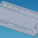
Cost Drivers in Liquid Cold Plate Manufacturing
The two largest cost drivers in cold plate manufacturing are the thermal conductivity requirements and the annual demand, factors that thermal engineers and manufacturing engineers often have limited or no control over. However, you can reduce costs by understanding how surface roughness, flatness, hardness, surface morphology, mounting features, and liquid connection specifications affect the cost of cold plates. By involving cold plate manufacturers early in the design process, you can identify manufacturing cost drivers and select the most cost-effective design.
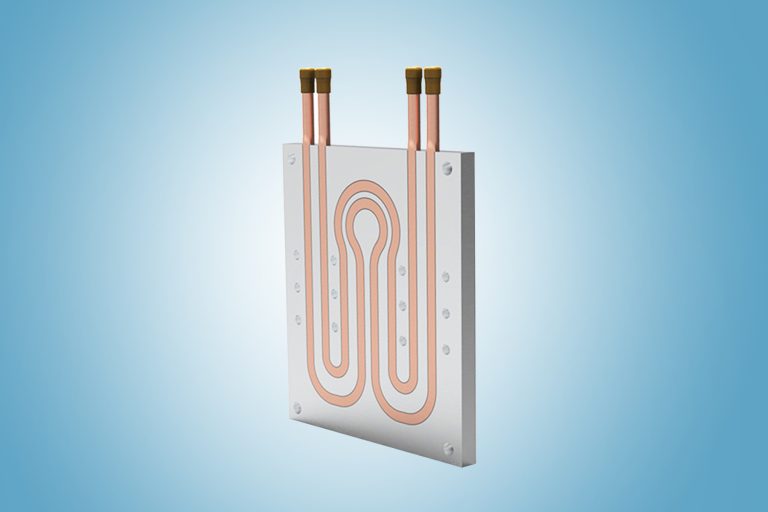
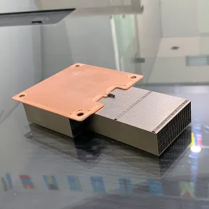
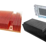
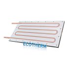
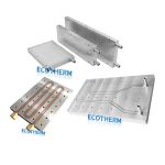
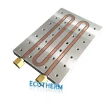
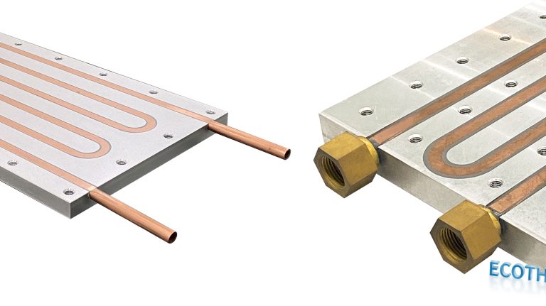
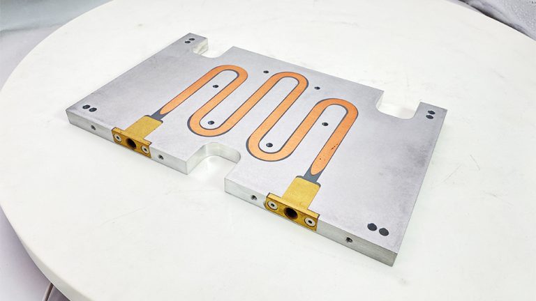
Most cold plates are made of aluminum, although some newer technologies use copper. While copper has better thermal conductivity, aluminum is more commonly used due to its lower cost, lighter weight, and ease of use. Copper processing is challenging and expensive. The two most popular aluminum cold plate technologies are tube and vacuum brazed designs (see Figure 1). Tube cold plates typically consist of copper or stainless steel tubes pressed into grooves of aluminum profiles. They offer excellent cost advantages and provide good thermal solutions for medium-to-low power density devices. Vacuum brazed cold plates consist of two metallurgically bonded plates with internal fins. These are available in various sizes and provide extremely high performance, making them ideal for applications with concentrated thermal loads. Both tube and vacuum brazed cold plate technologies are limited by their manufacturing lead times.
After the aforementioned factors, the largest cost driver for aluminum cold plates is machining time and additional processing steps. Cold plate manufacturers typically incur costs associated with machining time, including depreciation costs for machines, power, consumables, and maintenance. Therefore, the longer a cold plate spends in the manufacturing equipment, the higher the cost. Each additional processing step further increases the cost.
(1) Extrusions and Castings
To minimize machining time and reduce costs, it is ideal to use extrusions and castings as much as possible. Extrusion is the process of forcing metal through a mold to create an object with a fixed cross-section. Molds for new extrusions are relatively inexpensive, and the extrusion size is typically limited to about 9 inches (22.86 cm) in width. The wall thickness of extrusions needs to be relatively consistent, and any channels or features should be straight. Manufacturers can also combine extrusion and machining to lower costs. Certain features can be extruded, and more complex features can then be machined. This helps reduce extrusion costs, provided that extrusion features are considered during the design of the plate. Another option is to combine casting and machining to manufacture the cold plate. For instance, if the cast component is not flat enough, secondary operations may be required to achieve the necessary flatness specifications. Typically, the minimum order quantities for extrusion or casting are quite high, so you need the right application to justify the use of these processes. Both extrusion and casting can result in substantial cost savings at a larger scale.
(2) Surface Roughness
Surface roughness (finish) can significantly increase costs, yet its impact on performance is minimal. Contrary to some beliefs, roughness has relatively little effect on the thermal performance of a cold plate. In most applications, the surface contact between the cold plate and the component is less than 10%, or the air gap exceeds 90%. A smoother surface only slightly reduces the percentage of the air gap. A typical machined cold plate has a surface finish of 32-64 μin (81-163 μcm), which is adequate for most applications. Standard machining centers can reduce roughness to 16 μin (41 μcm), but this requires sturdier fixtures to minimize any potential vibration, as well as slower spindle speeds and feed rates. (Speed refers to the rate at which the cutting tool rotates, while feed rate refers to how fast the machine head moves across the cold plate. Reducing speed and feed rate means more machining time, thus increasing costs.)
In most applications, thermal interface materials (TIM) are used between the component or circuit board and the cold plate to minimize the gap. TIM should be as thin as possible since its relatively high thermal resistance significantly masks any improvements in thermal conductivity that might come from a smoother surface. Increasing the clamping force between the component or board and the cold plate can also help offset higher roughness, but it may add stress to the plate or component. When the cold plate and component or board heat up, the clamping stress also increases, exacerbating the effects of thermal expansion coefficient (CTE) mismatch.
(3) Surface Flatness
Compared to surface roughness, surface flatness has a more significant impact on the thermal performance of a cold plate, as unevenness dramatically reduces the contact area (see Figure 2). The standard flatness specification is 0.001 inches/inch (0.003 cm/cm). This means that within an inch of the measurement point, the lowest point of the cold plate should not be lower than 0.001 inches (0.003 cm) from the highest point. If a flatter tolerance than 0.001 inches/inch (0.003 cm/cm) is required, one cost-saving approach is to specify local flatness rather than demanding tight flatness across the entire plate. For example, if multiple insulated-gate bipolar transistors (IGBTs) are to be mounted on the cold plate, and each IGBT requires 0.001 inches/inch (0.003 cm/cm) flatness across the entire substrate, specify the local flatness for each individual IGBT rather than requiring the entire plate to be perfectly flat.
(4) Layout Design
Minimizing surface features is also crucial for reducing costs, especially for circuit board applications. Complex surface features typically require starting with a thick aluminum block, then machining away the unwanted material. This results in high raw material costs and excessive machining time. If surface features cannot be eliminated, bundling similar components on the circuit board can reduce machining requirements.
(5) Hardness
Cast, extruded, or vacuum brazed cold plates are very soft after processing, usually with a T0 hardness. The cold plate must be hardened, as soft aluminum is difficult to machine and handle. To increase hardness from T0 to T4, the cold plate must undergo heat treatment. The heat treatment process involves heating the cold plate to 1000°F (538°C), holding it at that temperature for about one hour per inch of cold plate thickness, and then rapidly cooling it to induce thermal shock (see Figure 3). One way to cool the cold plate is by dropping it directly from the furnace into a water bath. To further increase hardness from T4 to T6, artificial aging is required. This is done by placing the cold plate at 300°F-400°F (149°C-204°C) for 8-16 hours. T6 provides a very hard cold plate with high tensile strength, which is a typical requirement for military and aerospace applications. However, for most applications, T4 hardness is sufficient, and specifying T6 would only increase unnecessary costs.
(6) Mounting Features/Holes
Another cost-increasing factor in cold plate manufacturing is the addition of holes. A single hole can add up to $3 to the cost of the cold plate. One of the main reasons holes increase costs is that they cannot be drilled into the fluid path. Therefore, for tube-type cold plates, the tubes must be bent to accommodate the holes, and each bend adds to the cost. For vacuum brazed cold plates, an island must be created within the fluid path, which means performing electrical discharge machining (EDM) on the internal fins. This increases machining time significantly, thereby raising costs.
Strict tolerances on hole position and spacing also drive up costs. A reasonable tolerance specification is ±0.005 inches (±0.013 cm). As with flatness, specifying local tolerances wherever possible will help reduce costs. For large cold plates with holes spaced far apart, it becomes more challenging to maintain tolerances. One reason for this is that machine tool tolerances increase as the tool head moves further. Another reason is that thermal gradients of up to 18°F (10°C) may exist in machining shops, potentially causing the cold plate to expand or contract by as much as 0.005 inches (±0.013 cm). Through-holes are the easiest to specify with tighter tolerances because they are created with a single tool operation, whereas threaded holes are more challenging because they require two tools. Tapping holes are the most difficult to tolerance because the process requires a tapped hole, and the tap itself has tolerances. All of these tolerances combined make manufacturing more difficult and expensive. Avoiding small tapped holes also helps lower costs. Hole sizes of 4-40 or smaller become difficult to tap because the tap can break during drilling. To minimize this issue, machine speeds must be much slower. One way to address the strict tolerance requirements for cold plates is by increasing the size of the mounting holes on the component or circuit board.
(7) Liquid Connections
For liquid connections, straight-thread O-ring female ports typically perform best. They provide the best seal at the lowest cost, in addition to being compatible with welding systems. Pipe connections, such as NPT fittings, cannot provide the precision needed for components like cold plates. On vacuum brazed cold plates, it is best to avoid using external threaded fittings, such as barbs or bead fittings, as they require additional operations (e.g., welding) to connect the fittings. Furthermore, protruding fittings on the cold plate require protection during shipping, which can increase packaging costs. Quick-disconnect fittings should only be used when necessary, as their cost can reach up to $750 per pair. Cold plates or electronic devices that require frequent replacement should use quick-disconnect fittings. These are also necessary for cold plates that are pre-filled with coolant. Another consideration for liquid connections is the port tolerance. Typically, incoming pipes have some flexibility. A reasonable tolerance range is between ±0.030 inches (0.076 cm) and ±0.060 inches (0.152 cm).