Design and Performance Analysis of Embedded Tube Cold Plates for Liquid Cooling
With the development of electronic technology, electrical equipment is moving toward higher power density, miniaturization, and integration. The power loss of components such as IGBTs has reached several kilowatts in limited spaces, making traditional air cooling methods insufficient for meeting the cooling requirements of high-loss power components.
When the operating temperature of these components exceeds the specified range, their performance degrades, impacting system reliability, and local overheating can cause permanent damage to the chips. To better address the heat dissipation issues of power components, liquid cooling, with its compact structure, low noise, excellent thermal performance, and minimal environmental dependency, is being increasingly applied.
As a key component in liquid cooling systems, the structure and performance of cooling plates directly impact their ability to meet the heat dissipation requirements of electronic devices. Common types of liquid cooling plates include drilled cooling plates, O-ring assembled cooling plates, embedded-pipe cooling plates, and welded cooling plates. These different types vary in design, manufacturing process, thermal performance, cost, and other factors, each with its advantages and disadvantages.
- Drilled cooling plates are simple to manufacture and cost-effective, but they have relatively poor thermal performance and uneven surface temperatures.
- O-ring assembled cooling plates are also relatively low-cost but depend on O-ring seals, which can lead to leakage risks.
- Welded cooling plates offer good thermal performance, uniform temperature distribution, and design flexibility but come with high manufacturing costs and process complexity.
With the increasing demand for liquid cooling plates in civilian electronics, reducing costs and improving manufacturing efficiency, while still meeting heat dissipation and performance requirements, has become a critical factor. The choice of cooling plate design should be a comprehensive consideration.
This paper mainly introduces the design and manufacturing of embedded-pipe cooling plates and analyzes how different forming processes impact their thermal performance. An embedded-pipe cooling plate consists of copper or stainless steel pipes embedded within an aluminum substrate. Compared to welded cooling plates, embedded-pipe cooling plates have higher pressure resistance, fewer welding processes, better safety, lower pressure drop, simpler manufacturing processes, and lower costs. Various forming techniques are used in embedded-pipe cooling plates, including adhesive bonding, welding, and casting. The thermal performance of embedded-pipe cooling plates with different forming processes was simulated and compared using a finite element software.
1. Design of Embedded-Pipe Cooling Plates
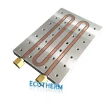
An embedded-pipe cooling plate consists of copper or stainless steel pipes embedded in the base plate. Several factors need to be considered when designing the cooling plate, such as weight, cost, operating environment, heat dissipation performance, corrosion resistance, and mechanical properties. Typically, an embedded-pipe cooling plate is made of a high thermal conductivity aluminum base plate and copper pipes. Common aluminum alloys used for the base plate include 5A06, 6061, and 6063, while the typical copper pipe used is soft copper pipe with a thickness of 0.5–1mm.
1.2 Base Plate Design
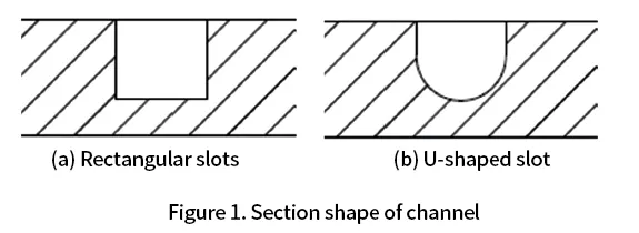
The design of the base plate in an embedded-pipe cooling plate mainly involves the channel cross-section and layout design. The channel cross-section shape generally takes two forms:
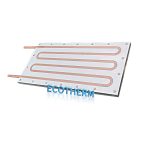
1.Rectangular grooves and U-shaped grooves (see Figure 1). Rectangular grooves are simpler to process, but the effective contact area between the copper pipe and the groove is smaller, which is less effective in heat transfer.
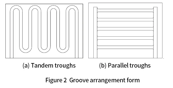
2.The layout of the grooves can either be in series or parallel (see Figure 2). The layout design needs to consider factors such as the distribution of heat sources, the position of other structural features, and the minimum bending radius of the selected copper pipe.
2. Manufacturing Processes of Embedded-Pipe Cooling Plates
The manufacturing processes for embedded-pipe cooling plates include adhesive bonding, welding, and casting. The forming process and requirements for each manufacturing method differ.
2.1 Adhesive Bonding Manufacturing Process
The adhesive bonding process is simple, cost-effective, and easy to operate. First, bent copper pipes are inserted into the grooves, and a small amount of high thermal conductivity epoxy resin is applied between the copper pipe and the groove. The copper pipe is then flattened to fill the groove, and the resin is allowed to cure at room temperature or through heat. Finally, the plate is processed using CNC to ensure that the copper pipe is flush with the cooling plate surface. However, due to the lower thermal conductivity of the epoxy resin, this method results in poor thermal performance.
2.2 Welding Manufacturing Process
Welded embedded-pipe cooling plates are produced by welding the copper pipes to the aluminum base plate. Welding aluminum to copper is challenging due to their significant differences in physical and chemical properties. Common welding methods include pressure welding, brazing, and various other forms such as cold-pressure welding, friction welding, flash welding, and explosive welding. Low-temperature brazing is often used with tin paste to improve welding performance.
2.3 Casting Manufacturing Process
The casting process involves embedding copper pipes in cast aluminum. This method benefits from the physical properties of metals, enabling a tight bond between the aluminum and copper, leading to minimal thermal resistance between the copper pipes and base plate, resulting in superior thermal performance. However, the need for molds makes this method costlier, though it is suitable for mass production.
3. Simulation of Thermal Performance for Embedded-Pipe Cooling Plates with Different Forming Processes
The impact of different manufacturing processes on the heat dissipation performance of embedded tube cooling plates primarily results from the varying thermal conductivity of the filling medium between the copper tubes and the substrate. For the same model, different thermal conductivities are set between the copper tubes and the substrate, and the heat dissipation performance is analyzed using finite element analysis software. The materials used in the model are aluminum alloy 6061 for the substrate and copper tube T2 for the copper tubes. The cooling plate dimensions are 286mm × 80mm × 10mm, and the simulated heat source has dimensions of 40mm × 40mm, with a total of 5 heat sources distributed across the cooling plate. The total heat dissipation power is 3000W, the coolant is water, the flow rate is 4L/min, the inlet temperature is 30°C, and the ambient temperature is 30°C. The simulation model is shown in Figure 3.
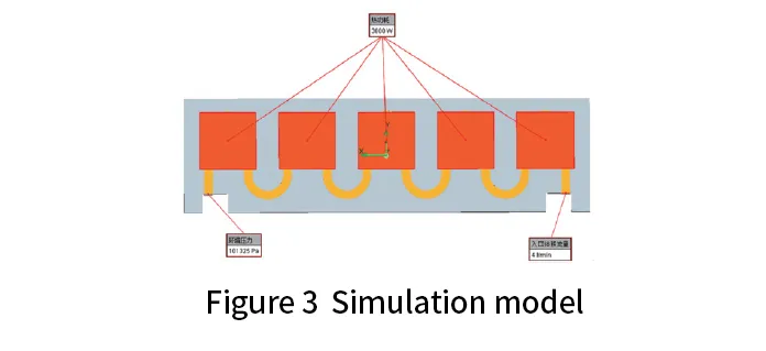
The following assumptions were made during the simulation:
1. The material property parameters in the model are considered constant;
2. The fluid is incompressible;
3. Radiative heat dissipation from the cooling system is not considered;
4. The contact thermal resistance between the simulated heat source and the cooling plate is not considered.
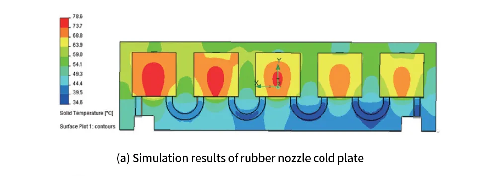
3.1 Simulation of the Cooling Performance of Epoxy
Bonded Embedded Tube Cooling Plates
In the epoxy bonded embedded tube cooling plate, the substrate and copper tube are bonded using a heat-resistant epoxy resin with a thermal conductivity typically ranging from 5 to 10 W/m·K. During bonding, the thickness of the epoxy resin is controlled between 0.1 and 0.2 mm. In the simulation, an epoxy resin material is applied at the contact interface between the copper tube and the substrate, with a thermal conductivity of 5 W/m·K and a thickness of 0.2 mm.
The simulation results are shown in Figure 4(a).
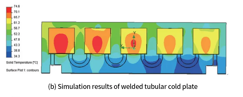
3.2 Simulation of the Cooling Performance of Welded Embedded Tube Cooling Plates
In the welded embedded tube cooling plate, the substrate and copper tube are joined using solder paste, with a thermal conductivity typically ranging from 40 to 60 W/m·K. During welding, the thickness of the solder paste is controlled between 0.1 and 0.2 mm. In the simulation, solder paste material is applied at the contact interface between the copper tube and the substrate, with a thermal conductivity of 40 W/m·K and a thickness of 0.2 mm. The simulation results are shown in Figure 4(b).
3.3 Simulation of the Cooling Performance of Cast Embedded Tube Cooling Plates
In the cast embedded tube cooling plate, the substrate and copper tube are in close contact, resulting in minimal contact thermal resistance. In the simulation, it is assumed that the substrate and copper tube are perfectly bonded, with no contact thermal resistance. The simulation results are shown in Figure 4(c).
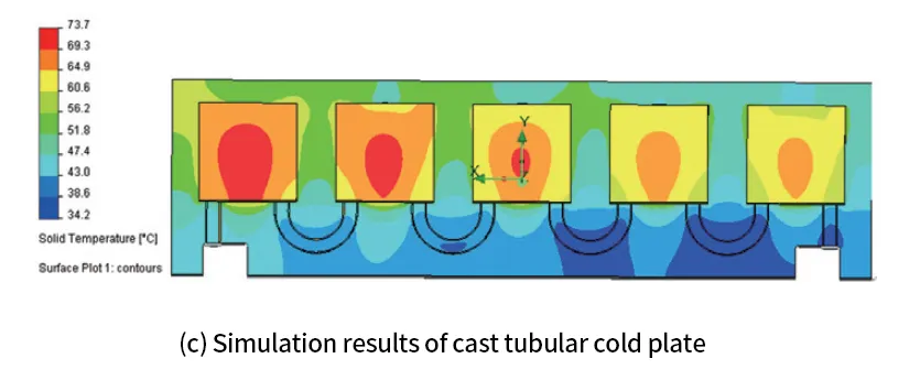
The simulation results indicate that the filling medium between the substrate and copper tube in the embedded tube cooling plate has a significant impact on its cooling performance. The higher the thermal conductivity of the filling medium, the better the contact, and thus the higher the cooling performance of the cooling plate. The cooling performance of the adhesive-bonded embedded tube cooling plate is relatively poor, which is due to the low thermal conductivity of the thermally conductive epoxy resin adhesive used, resulting in significant thermal resistance between the substrate and the copper tube. The cooling performance of the welded and cast embedded tube cooling plates is nearly identical, primarily because the thermal conductivity of the solder paste is relatively high, and the thickness of the filling medium between the substrate and copper tube is small, resulting in minimal impact.
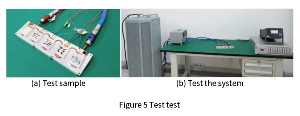
4.Experimental Testing
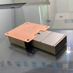
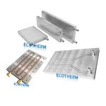
The cooling performance of embedded tube cooling plates produced using different manufacturing processes was tested. The substrate material of the cooling plate is aluminum alloy 6061, and the copper tube material is copper. A heating resistor sheet was used as a simulated heat source, powered by a DC power supply, with the total power adjusted to 3000W. The test sample was connected to a liquid cooling source through piping, with the flow rate set to 4L/min and the inlet temperature set to 30°C. The shell temperature of the simulated heat source was measured using a multi-channel temperature acquisition instrument. The test sample is shown in Figure 5(a), and the test system is shown in Figure 5(b).
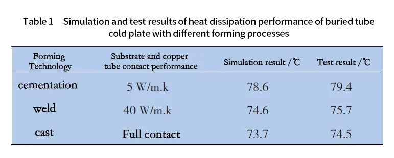
The comparison between the simulation and testing results of the cooling performance of embedded tube cooling plates manufactured using different forming processes is shown in Table 1. The test results are in good agreement with the simulation results.
With the widespread application of liquid cooling technology in the heat dissipation systems of electronic devices across various fields, the requirements for product reliability and cost have become increasingly stringent, driving the diversification of liquid-cooled plate designs. Embedded tube cooling plates offer advantages such as simple manufacturing processes, reliable performance, and low cost, making them widely used across various sectors, particularly in the consumer electronics field.
Through a comparative simulation analysis of the cooling performance of embedded tube cooling plates manufactured by different processes under the same parameters, it can be concluded that, due to the thermal resistance between the substrate and the copper tube, cast embedded tube cooling plates exhibit the best heat dissipation performance, followed by welded embedded tube cooling plates, while adhesive-bonded embedded tube cooling plates perform relatively poorly. These findings are consistent with the experimental results.
The manufacturing of embedded tube cooling plates can be achieved through adhesive bonding, welding, or casting, with each process having its own advantages and disadvantages. When designing a product, factors such as production capacity, process feasibility, product performance, and cost-effectiveness should be comprehensively considered to determine the most suitable manufacturing method. Research on the design and manufacturing processes of embedded tube cooling plates should continue to focus on optimizing fluid channel layout designs and developing new substrate-to-copper tube assembly techniques, to ensure the development of higher-performance, more reliable embedded tube cooling plates that can be applied in a wider range of applications.