Creating an Efficient Liquid Cooling Solution: Design and Testing Methods of Liquid - Cooling Plates
1.1 Cold Plate
1.1.1 Description of the Cold Plate
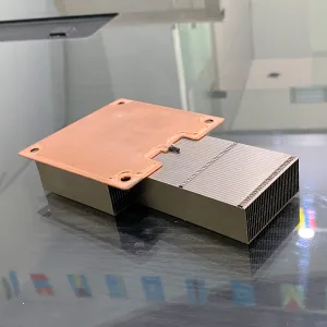
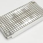
The cold plate is a heat sink with integrated pipes or flow channels, allowing a liquid to flow through the heat sink to dissipate heat. The cold plate is installed on processors and other electronic components that require cooling, providing a path for heat to be transferred to the coolant. The design of the cold plate can be divided into single-phase or two-phase coolant types, and it can be optimized for specific coolants to maximize the heat dissipation performance. For example, a simple cold plate may be a metal block with integrated pipes, while a complex design may include milled or molded micro-flow channels to enhance the thermal performance.
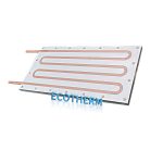
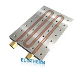
For a cold plate assembly with integrated pipes, the cold plate typically consists of a fluid heat exchanger containing flow channels and a fixing bracket. The fluid heat exchanger is connected to the pipes through metal connection processes such as welding, brazing, or soldering. For cold plates using machined or molded flow channels, their components include a flow channel heat exchanger, a fixing bracket, and a fluid connector (Figure 1). The fluid connector is installed on the heat exchanger to guide the coolant to flow through the flow channels. The connector is fixed to the pipe with a hose clamp, while the fixing bracket provides structural support for the component stack and ensures the precise positioning of the heat exchanger on the processor.
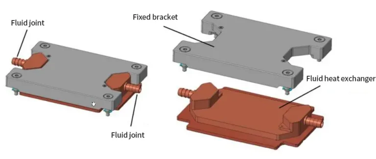
The cold plate fluid connector is installed on the fluid heat exchanger of the cold plate and serves as the interface between the cold plate and the coolant circulation. The design of the cold plate fluid connector can be optimized for specific flow rates, system dimensional tolerances, and fluid circulation configurations, while minimizing fluid stagnation. Throughout the service life of the cold plate, the design and installation of the cold plate fluid connector need to ensure a sealed and leak-free connection.
1.1.2 Types of Cold Plates
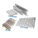
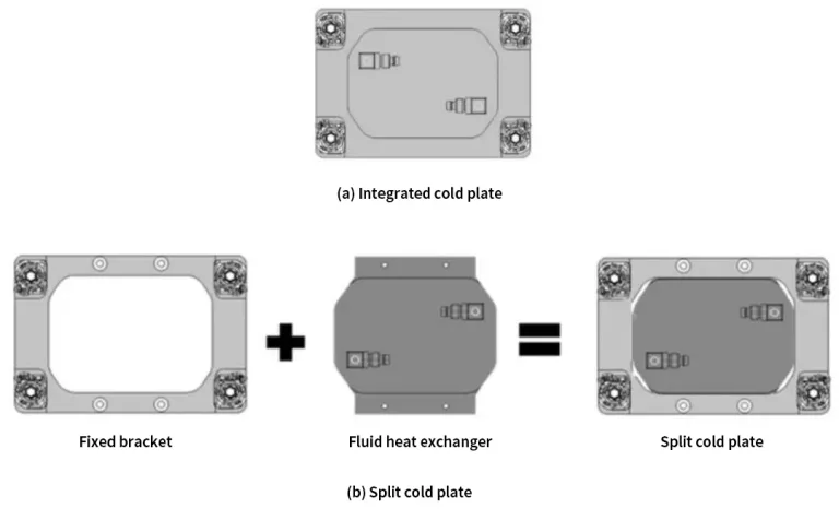
Cold plates can be divided into integrated cold plates (see Figure 3(a)) and split cold plates (see Figure 3(b)). In an integrated cold plate, the fluid heat exchanger and the retaining bracket are integrated and inseparable. Since the retaining bracket is integrated into the cold plate design, it is difficult to redeploy the integrated cold plate across different processor generations. In contrast, for a split cold plate, the fluid heat exchanger and the retaining bracket are separate components. This modular design supports redeployment across multiple processor generations by redesigning the retaining bracket suitable for the newer processor series and reusing the fluid heat exchanger, which is a cost-saving option. Schematic diagrams of the two types of cold plates are shown in Figure 3 below.
1.1.3 Cold Plate Manufacturing and Assembly
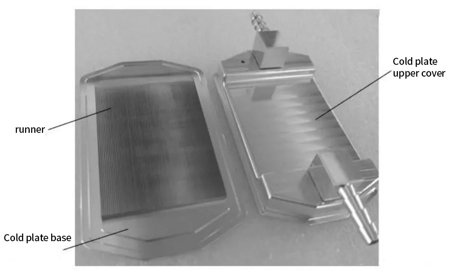
The main manufacturing processes for the top cover plate of the heat exchanger and the cold plate base include brazing, friction stir welding, soldering, and O – ring – based sealing. Table 1 below describes some of the advantages and disadvantages of the specific manufacturing processes used for assembling the cold plate heat exchanger.
Table 1: Comparison of Cold Plate Manufacturing Processes
| Manufacturing Process | Advantages | Disadvantages |
|---|---|---|
| Brazing | – Supports higher working pressures – Brazed fins can enhance rigidity | – High cost – Need to consider the chemical compatibility of the filler metal – Copper is annealed during brazing, reducing rigidity |
| Friction Stir Welding (FSW) | – Supports integrated/split – type designs – Does not cause copper annealing | – High cost – Long process time – Requires more material for the weld seam |
| Soldering | – Lower cost compared to brazing/FSW – Does not cause copper annealing | – Need to consider the compatibility of the solder – Cannot weld fins – Solder joints are prone to embrittlement and porosity |
| O – ring | – Low cost – Supports non – metallic materials – Supports complex flow channel designs | – Low working pressure – Poor sealing reliability – Short service life – Prone to leakage at high temperatures |
1.2 Cold Plate Assembly
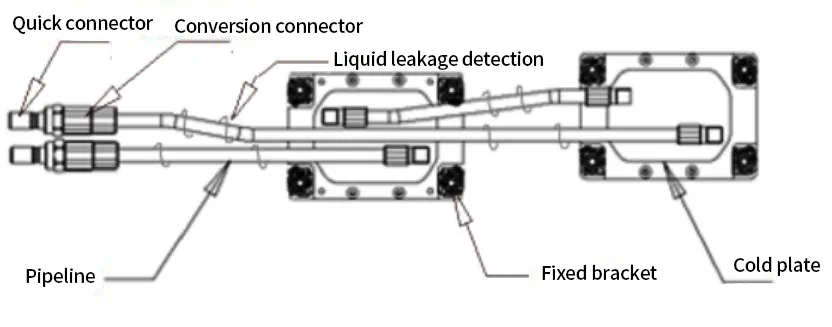
The cold plate assembly consists of a cold plate, coolant pipes, and quick connectors. Optional cold plate components include transition connectors and leak detection hardware, which can be integrated according to the customer’s product design requirements. A schematic diagram of the cold plate assembly is shown in Figure 4. The additional components required to support the cold plate are described as follows:
1.3 Cold Plate Technology Cooling System
The cold plate technology cooling system consists of IT equipment (ITE), cold plates, coolant piping, quick disconnects (QDs), blade manifolds, secondary cooling loops, coolant distribution units (CDUs), facility water systems (FWS), and cooling towers or chillers. This system supplies coolant to the cold plates at a constant temperature and pressure. Figure 5 illustrates a schematic diagram of a cold plate liquid cooling system. All wetted materials in the cold plate technology cooling system must be compatible with the coolant.
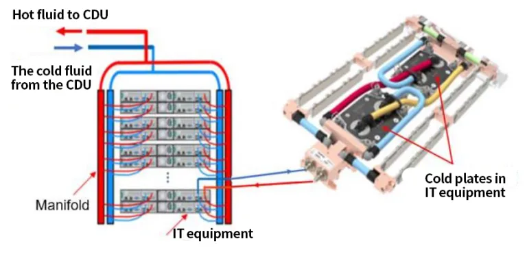
Figure 5: Schematic Diagram of Cold Plate Liquid Cooling Loop (Technology Cooling System—TCS)