High-Efficiency Liquid-Cooled Thermal System Design for Data Centers

Introduction

The accelerated application of digital economy such as artificial intelligence, 5G communication, online shopping, mobile payment and health code scanning is supported by supporting data centers. In data centers, the main factors affecting energy consumption are: IT equipment, cooling systems, power supply systems, etc., among which IT equipment accounts for 50% of the total energy consumption of data centers, and cooling systems account for 37% of the total energy consumption. The energy consumption of IT equipment belongs to basic energy consumption, which is difficult to significantly reduce in a short time; reducing the energy consumption of cooling systems and making them operate efficiently have become the primary goals of energy conservation and consumption reduction.

1 Composition of the Data Center Cooling System

Most of the electrical energy consumed by IT equipment is converted into waste heat. To ensure that IT equipment operates normally at appropriate working temperatures, data centers are equipped with refrigeration and cooling systems including chillers, cooling towers, and precision air conditioners to discharge waste heat from the data center. The heat transfer process is shown in Figure 1. Among them, chillers, cooling towers, water pumps, and precision air conditioners are the key focuses for energy consumption.

Figure 1 Heat-transfer-diagram-of-the-data-center
At present, the heat transfer media in data centers are basically air or water. Among them, the constant-pressure specific heat capacity of water is 1.004 kJ/(kg·K), and its specific heat capacity is 4,200 kJ/(kg·K) [3]. The heat-carrying capacity of water is approximately 1,000 times that of air. Therefore, using water as a heat dissipation medium in the design of cooling systems is an effective energy-saving measure. To improve the energy efficiency of the refrigeration system, the following strategies are adopted:
  • Heat Collection Side: High-efficiency heat sinks and precise air supply are used to transfer heat out.
  • Precision Air Conditioning Side: The cooling system has evolved from room-level refrigeration to modular machine room and rack-level refrigeration, which is closer to the heat source and reduces energy consumption during refrigerant transportation.
  • Cold Source Preparation Link: The system has shifted from air cooling to water cooling and natural cooling to improve external heat transfer efficiency.
In traditional cooling systems, precision air conditioners, chillers, and cooling towers have their own control systems and operation strategies. Although efficiency optimization has been achieved at the local level and individual components have reached optimal performance, overall cooling efficiency still needs further improvement.
To systematically improve cooling efficiency, it is necessary to carry out collaborative management and refined control from end to end, including heat collection, cold source preparation, and external heat transfer, so as to reduce the power consumption of the cooling system.

2 End-to-End Liquid Cooling System Design

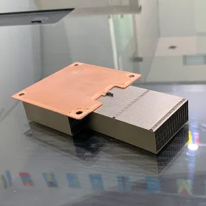
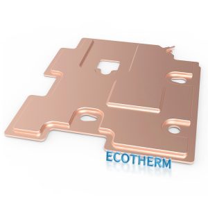
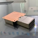
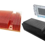
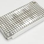
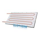
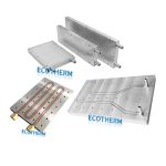
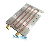
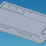
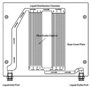
2.1 Board-Level Liquid Cooling Design

With the explosive growth of computing power demand, the integration level and power consumption of CPUs and GPUs have increased exponentially, with single-chip power consumption climbing to 300W. Traditional chip heat sinks and air-cooling solutions have encountered cooling bottlenecks. As the source of heat, how to transfer heat from the inside of the chip is the primary problem to be solved by the data center cooling system.
From the perspective of the heat dissipation path, the heat generated by the chip first needs to be transferred from the inside of the chip to the board-level heat sink. A more efficient heat sink solution is more conducive to heat collection.
For single chips with a power consumption of less than 200W and IT equipment with a single-rack power consumption of less than 20kW, air can continue to be used as the heat transfer medium. Heat pipe heat sinks and VC (vapor chamber) heat sinks, combined with TIM (thermal interface material) with high thermal conductivity (such as graphite sheets/graphene), effectively reduce the thermal resistance between the chip and the heat sink substrate and improve the cooling efficiency of the heat sink.
For single chips with a power consumption of more than 200W and IT equipment configurations with a single-rack power consumption of more than 20kW [5], continuing to use air as the heat transfer medium can no longer effectively transfer the heat generated by the chips, requiring the use of liquid working fluids for heat dissipation. Liquid cold plate cooling is a relatively mature board-level chip cooling technology currently available.


A liquid cold plate includes an inlet connector, an outlet connector, an upper cover plate, and a bottom plate. The upper and bottom plates are connected by vacuum brazing to form a sealed liquid heat exchange cavity. Inside the cavity, distribution chambers and flow guide grooves of different widths are designed according to the chip’s position and heat dissipation requirements. This achieves throttling control of liquid flow, increases turbulence, enhances the cold plate’s local heat dissipation capacity, and eliminates the heat dissipation bottleneck of hotspots caused by high-power chips. The internal structure is shown in Figure 2.
Figure 2.Cross-sectional-view-of-the-liquid-cooled-cold-plate
In the same rack, there are different types of single boards with varying power levels and hotspots. However, the liquid supply pressure at the inlet connector of the liquid supply pipeline is basically the same, so throttling control is required through the distribution chamber of the cold plate. For single boards with lower chip power consumption, throttling control is used to reduce the flow supply of the working fluid.


In the actual design of liquid-cooled cold plates, CPUs, memory, and other high-power devices are covered, but most components such as resistors and capacitors are not covered, generating a small amount of residual heat that needs to be dissipated by fans. This results in the coexistence of liquid cooling and air cooling in the system, leaving room for improvement in heat dissipation efficiency. In cold plate design, 100% liquid cooling can be technically achieved by covering all components with TIM materials, but this increases the cost and complexity of the cold plate. While pursuing efficient heat dissipation, the initial cost investment must also be comprehensively considered. If the types of node single boards are uniform, fully covered single boards can be considered, and the initial cost can be offset by cost reductions brought about by increased shipment volumes, thereby achieving a balance between energy conservation/carbon reduction and investment.


For cold plate cooling, the liquid working fluid is typically deionized water, which has a high specific heat capacity, can quickly absorb heat, and is non-corrosive, with no impact on pipeline reliability. Cold plate liquid cooling is an indirect liquid cooling method, where the chip does not directly contact the liquid working fluid, offering high reliability and mature technology. However, there is thermal resistance between the chip and the liquid working fluid, prompting some manufacturers to promote immersion liquid cooling solutions. In this approach, IT equipment is submerged in a circulating cooling liquid, with the chip in direct contact with the liquid cooling fluid, reducing thermal resistance. Additionally, the phase change process of the working fluid carries away more heat, making it a new hotspot in liquid cooling. The most commonly used working fluid for immersion liquid cooling is fluorinated liquid, but its current high cost has become an obstacle to large-scale commercialization.

2.2 Rack-Level Liquid Cooling

In data centers, IT equipment is arranged in racks. Racks are used to house information equipment such as servers, storage devices, and network switches. While board-level cooling transfers heat from individual IT devices, the entire rack is still required to collect and transfer heat to the outdoors. The main components of rack-level liquid cooling include inlet/outlet manifolds, monitoring units, temperature sensors, solenoid valves, and check valves, as shown in Figure 3.
Figure 3 Rack-level-liquid-cooling-configuration-diagram
The inlet/outlet manifolds are externally connected to the machine room-level liquid cooling distribution unit, and internally connected to the inlet and outlet connectors of the liquid cooling cold plates through quick connectors. System heat is transferred to the outside of the rack through the manifolds.
The main functions of solenoid valves and check valves are to control the flow of liquid and prevent the failure range from expanding beyond a single rack in the event of a leak.
Temperature sensors are primarily used to real-time monitor the inlet and outlet water temperatures. By utilizing the temperature difference between inlet and outlet water, the opening degree of solenoid valves is controlled to regulate the inlet/outlet water flow, ensuring that heat and flow are matched.
Although the deionized water used as the working fluid in the liquid cooling system is theoretically non-conductive, dust particles and impurities on circuit boards or electronic components can cause short circuits when in contact with deionized water. This remains the greatest resistance and concern in the implementation of liquid cooling. To address cold plate leakage issues, control measures must be taken in three aspects: quality control, scruple
leakage monitoring, and prevention of sudden major leaks.
Quality control covers both production and installation phases:
  • Production phase: Ensure reliable processes, conduct 100% pressure tests on cold plates, and use ultrasonic sampling for flaw detection; verify the effective number of insertions/extractions and long-term reliability of quick-plug connectors.
  • Installation phase: Ensure secondary pipelines are thoroughly flushed before installation to prevent blockages in quick connectors, spring jams, or rubber ring failures caused by impurity particles, which could lead to leaks during operation. These measures primarily aim to minimize the occurrence of leaks.
For minor leaks in cold plates, detection and alarm systems must be implemented to prompt maintenance personnel for timely repairs. Two detection methods are available:
  1. Water immersion sensor detection: Sensors are installed on water collection trays, which not only facilitate leak detection but also prevent liquid from spilling outside the rack to limit fault spread. While mature and reliable, this method can only detect leaks after the working fluid has accumulated in the tray through hardware boards and rack installations—by which point significant leakage may already have damaged boards and components.
  2. Real-time monitoring: Tracer substances with low boiling points are mixed into the working fluid. When a leak occurs, built-in gas sensors on the boards detect the tracer.
For sudden major leaks (low probability but high impact), check valves are added at the inlet/outlet pipe entrances of the rack-level manifolds to close unidirectionally when a significant pressure difference occurs.

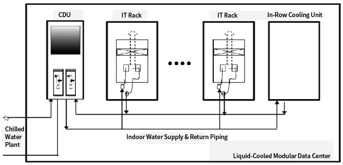
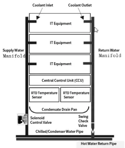
2.3 Machine Room-Level Liquid Cooling Design

Machine room-level heat dissipation aims to transfer the heat emitted from racks to the outdoors. The machine room-level liquid cooling solution includes liquid-cooled modular machine rooms, chillers, water pumps, cooling towers, pipelines, etc., as shown in Figure 4.

Figure 4.Computer-room-level-liquid-cooling-configuration-diagram
Under normal circumstances, a liquid-cooled modular machine room includes 2 backup liquid cooling distribution units (CDUs), 10-20 IT racks, 1-2 row-level air conditioners, and power supply and distribution equipment, as shown in Figure 4.


The liquid cooling distribution unit (CDU) is used to distribute the liquid working fluid among IT liquid-cooled racks, providing functions such as secondary-side flow distribution, pressure control, physical isolation, and anti-condensation. In actual operation, the CDU supplies cooling water at a specific flow rate and temperature to the IT liquid-cooled racks. The cooling water enters the liquid-cooled cold plates through the manifold, carrying away heat generated by processors and critical components. The heated cooling water then returns to the intermediate heat exchange unit of the CDU, releasing heat into the outdoor return water pipeline. This heat is subsequently discharged to the outdoor environment through chillers or dry coolers, completing the heat management for liquid-cooled servers.


The CDU regulates the temperature and flow rate of the working fluid sent to the liquid-cooled cold plates to provide cooling capacity to IT racks, serving as a cooling capacity distribution hub. Its internal heat exchange unit also isolates the modular machine room from the outdoor liquid supply circuit. Due to the critical role of CDUs, they typically adopt a 1+1 backup configuration. The CDU controls the flow rate of the liquid working fluid by detecting the inlet/outlet water temperature and supply pressure and adjusting the rotational speed of the supply water pump. Most current CDU control systems do not link with temperature detection inside the racks, resulting in relatively coarse control. To address this issue, some applications have replaced centralized CDUs with distributed CDUs integrated into the racks, allowing the CDU’s flow regulation to fully adapt to the service operation status and power consumption fluctuations within the racks. Centralized CDUs are suitable for scenarios with a large number of liquid-cooled racks that can be integrated into a modular machine room, while distributed CDUs are ideal for deployments with only 2-3 liquid-cooled racks due to their flexibility.

3 Conclusion

Driven by the dual-carbon goals, data centers carry a dual mission: on one hand, they provide abundant computing power for the digital economy through intensive and large-scale operations. Under the traction of data center computing power efficiency, the widespread use of high-density racks and high-power chips has pushed traditional air cooling to its limits; on the other hand, they reduce their own energy consumption through various technologies such as high-efficiency liquid heat sinks, dry coolers (natural cold sources), etc. After adopting liquid cooling, heat dissipation efficiency has significantly improved , with the energy consumption proportion of the cooling system reduced from 37% to approximately 10%, achieving remarkable energy conservation and carbon reduction effects. If 50% of new data centers nationwide adopt liquid cooling, it could save 45 billion kWh of electricity and reduce carbon dioxide emissions by 3 million tons annually.


Latest Blog

From Concept to Mass Production – Your Professional Heat Dissipation Solution Partner

Scroll to Top

contact Ecotherm

We are available to assist you via email. Please don’t hesitate to get in touch, and we will respond to your inquiry as soon as possible.


Email:  support@ecothermgroup.com

Follow us on YouTube | TikTok | LinkedIn
Stay connected with us for updates, news, and more!


Please fill out the form below, and we will get back to you as soon as possible.

Contact Ecotherm

Please upload your design or requirements, and our experts will provide a precise cooling solution tailored to your needs.