Analysis of the Heat Dissipation Principles of High-Power LED Automotive Lights
With the booming development of the automotive industry, high-power LED modules—once only equipped in high-end models with attractive designs and superior optical performance—are gradually being promoted extensively in mass-market A-class vehicles and the aftermarket. Especially with the widespread use of LED light sources in automotive lamps, the large-scale adoption of high-power LEDs in automotive headlights is a future trend. Therefore, as lenses serve as the main components of exterior lighting, effective heat dissipation of high-power LEDs remains a critical task throughout the headlamp design phase.
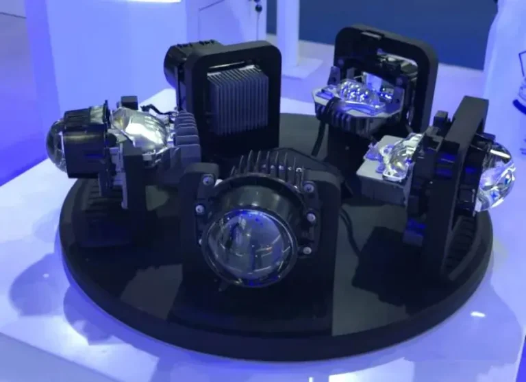
High-power LEDs in automotive headlights are primarily used for both high beam and low beam functions. From an appearance standpoint, they can be roughly divided into two categories: reflector-type and lens-type.
LED Daytime Running Lights - Reflective Type
LED Daytime Running Lights - Lens Type
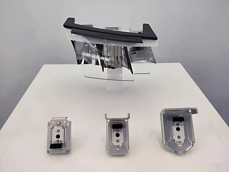
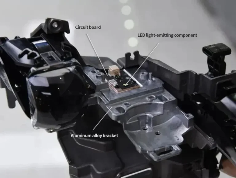
The internal structure of a vehicle's near and far light module
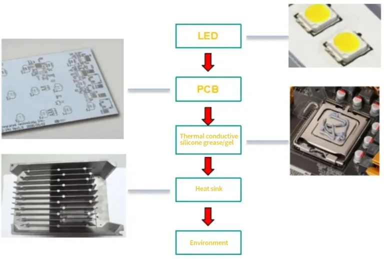
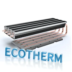
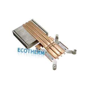
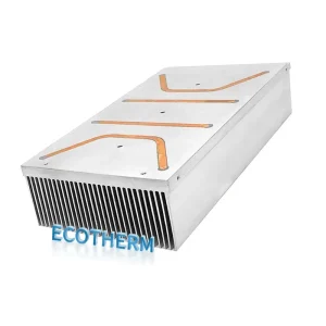
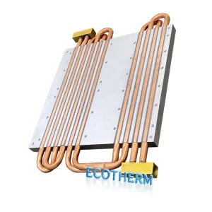
However, regardless of whether the appearance is reflector-type or lens-type, the thermal model is the same: the heat generated by the high-power LED is transferred through a metal substrate to the rear heatsink, which then dissipates the heat into the surrounding air through its large surface area. The heat dissipation path is shown in the figure below:
The heat dissipation path of high-power LEDs
Below is an introduction to the heat dissipation mechanism of each component along the heat dissipation path:
LED
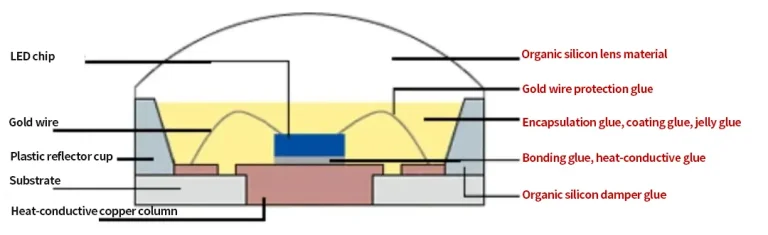
The internal structure of LED
Many people simply perceive the LED as a heat source in the thermal model—like the bulb in a halogen lamp—and do not consider how it affects heat dissipation. In fact, this is not the case. More precisely, the heat source within an LED is the wafer portion inside the LED package, commonly referred to as the junction. When the temperature at the junction is conducted outward to the exterior of the LED package, the performance differences among various LEDs become apparent. Specifically, an LED’s datasheet defines the thermal resistance from the junction to the solder pad. The smaller this value is, the better the LED’s heat dissipation performance. This factor is especially critical in applications involving high-power LEDs.
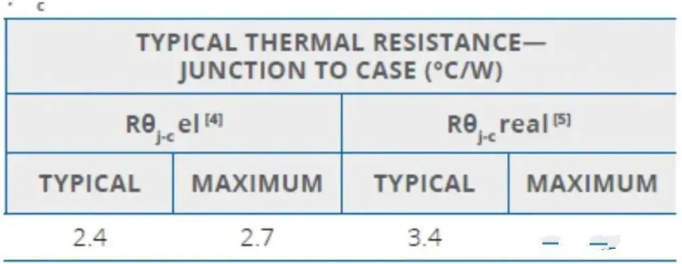
The definition of thermal resistance in the LED specification document
Definition of Thermal Resistance in LED Datasheets
PCB
The PCB serves as the main carrier for LED soldering and wiring. It must both ensure proper circuit layout and meet the heat dissipation requirements of electronic components—both aspects are essential. When discussing PCB selection, we must consider two types: FR4 and metal substrates. The former offers advantages such as ease of wiring and double-sided layouts but has poor heat dissipation performance and is rarely used in high-power LED applications.
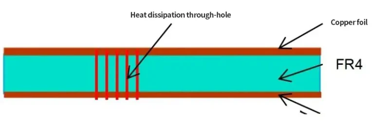
Adding vias to the FR4 board improves the heat dissipation performance.
Of course, FR4 boards can improve heat dissipation by using vertical thermal vias to conduct heat into the copper foil underneath, thereby enhancing cooling capability. However, because the copper content in the vias is quite low, this improvement is still far less effective than metal substrates, so FR4 is mostly used in low-power applications.
In contrast to FR4, one of the widely used metal substrates for high-power LEDs is the aluminum substrate. It has the advantage of high thermal conductivity of the metal base material, allowing heat to be quickly conducted away from the heat source. The downside is that wiring can only be arranged on one side, and the cost is relatively high, making it the preferred solution for high-power modules such as high and low beam headlights.
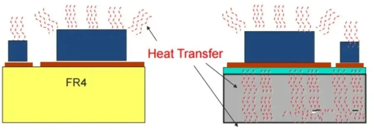
PCB heat dissipation schematic diagram (FR4 on the left, metal substrate on the right)
From the heat dissipation diagram above, it is clear that the superior cooling performance of metal substrates stems from their high thermal conductivity. Compared to FR4, metal substrates can enhance heat conduction at the bottom and make better use of the PCB’s heat dissipation area.
It is worth noting that even among metal substrates, differences in the formulation of the insulating layer and slicing processes used by different manufacturers can lead to variations in heat dissipation performance.
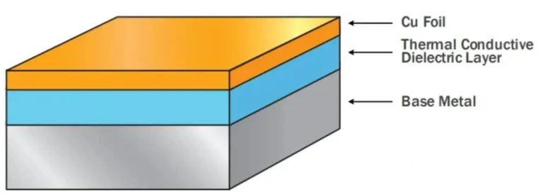
Schematic diagram of the structure of the metal substrate
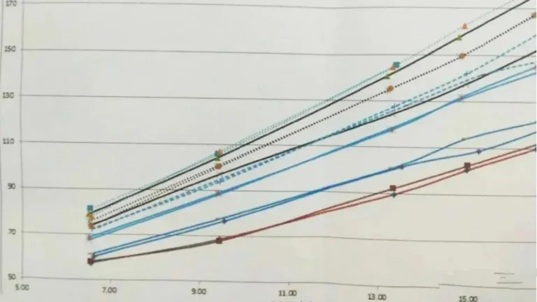
The temperature performance of different types of metal substrates
Thermal Grease / Thermal Adhesive
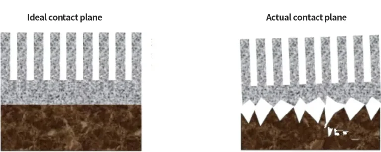
In actual products after processing, the contact surface between the PCB and the heatsink is microscopically composed of point contacts, which is quite different from the ideal face-to-face contact assumed in the design. The initial design goal is to directly transfer heat from the PCB to the base of the heatsink. However, the rough contact surfaces in the real product cause many air gaps to fill the interface. These air pockets form a thermal resistance layer that prevents heat flow to the heatsink. Therefore, certain filling materials are needed to eliminate the air between the two surfaces, which is why thermal interface materials such as thermal grease or thermal adhesive are used.
At the microscopic level, the contact surfaces of the ideal and actual parts
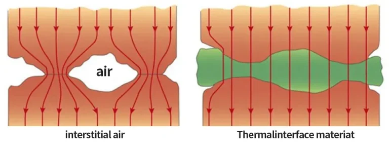
The distribution of heat flow direction before and after filling the thermal insulation material