Applications of Aluminum Alloy Heat Sinks in Thermal Management Solutions
Heat Sink Fundamentals
A heat sink is one of the most essential components for cooling electronic devices. For any heat source that cannot dissipate heat adequately through passive conduction and requires more efficient cooling than basic solutions, a custom heat sink is necessary to transfer heat away from the source and optimize dissipation via conduction or convection.
A heat sink typically consists of a base and fins. The base, a flat plane in contact with the heat source, spreads thermal energy to the fins. Fins are designed in various geometries, often perpendicular to the base, to maximize surface area for heat dispersion.
Most heat sinks are made of thermally conductive metals, primarily extruded aluminum heat sinks (235 W/mK conductivity), which are lightweight and cost-effective. Copper (400 W/mK) is also used for high-performance applications despite its higher cost and weight.
Heat sinks are categorized into natural convection (passive) and forced convection (active). Passive designs maximize surface area without active components, while active solutions integrate fans or blowers to enhance cooling through turbulent airflow.
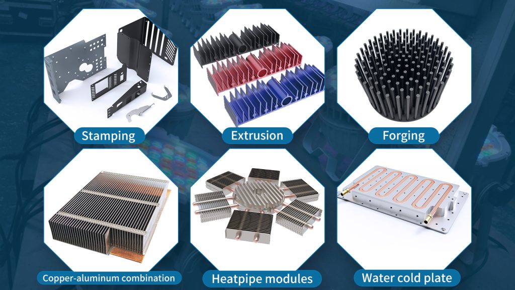
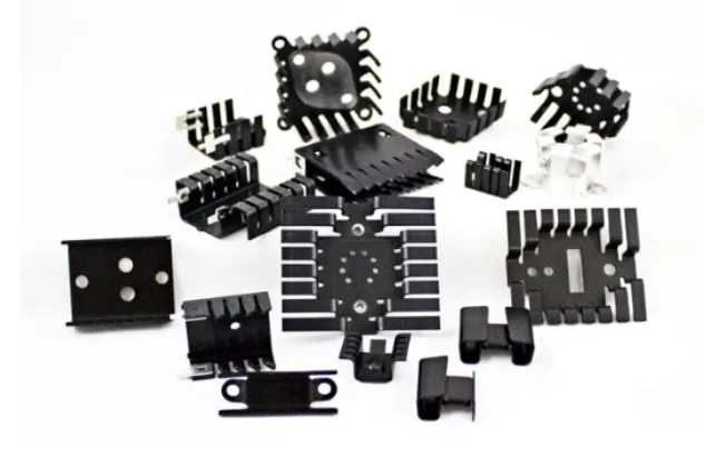
01 Stamped Plate Level
Plate-level heat sinks can be stamped or extruded. Stamped heat sinks are made from sheet metal through a progressive stamping process where each metal stamping piece adds details and features as it passes through the stamping die. The geometries of stamped heat sinks are designed specifically for certain electronic packaging types to ensure an optimized fit and function on the PCB. These heat sinks can be passive or active, depending on whether a fan is added, which is typically used to increase airflow across the entire circuit board or system.
Advantages
• Ideal for low-power applications (0-5W)
• Quick and easy assembly options
• Low cost
• Scalable for high volumes
• Catalog options for all packaging types
Disadvantages
• Not suitable for applications above 5W
• Size limitations, typically no larger than 50mm
• Can only be used on a single device – not suitable for cooling multiple heat sources.
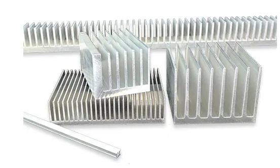
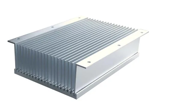
02 Extruded Aluminum
Extruded aluminum is one of the most popular and cost-effective manufacturing methods. The size of extruded heat sinks varies depending on the application; they are smaller for board-level applications and larger for medium-power applications. They can be designed for passive or active cooling based on fin shape and spacing. Board-level extruded heat sinks are common in BGA and FPGA packages.
Choosing the right extruded heat sink depends largely on the desired profile. Extruded heat sinks are made by creating a profile die that determines the fin density, spacing, length, as well as the base height and width. Softened aluminum is pushed into the die to form a long bar, called an extruded billet, with the same profile and dimensions as the die. The billet is then cut into smaller standard-shaped rods/rectangles or custom lengths, which are further processed to create custom heat sinks. This process is fast, cost-effective, and scalable, which is why many people consider extrusion heat sinks first when looking for solutions.
Advantages
• Ideal for medium to low power applications
• Fast and cost-effective
• Scalable for high volumes
• Simple customization
• Integrated structure with limited thermal resistance
Disadvantages
• Not suitable for high-power applications
• Size limitations, typically no larger than around 23 inches wide and 47 inches long
• Processing limits for larger sizes.
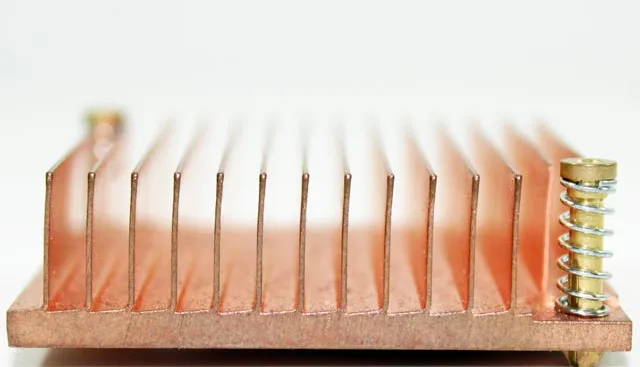
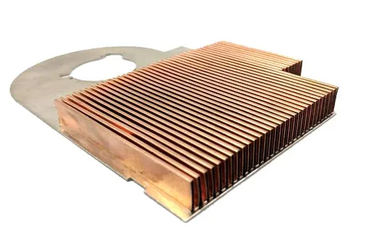
03 Skiving Heat Sinks
Skiving is a manufacturing process where a single block of metal is used to create a product by cutting thin layers from the top part of the base. These layers are folded up to be perpendicular to the base and the process is repeated to create the fins. The integrated structure reduces thermal resistance since there are no seams or material gaps between the fins and the base. This method also enables high fin density and thin fin geometries, resulting in a larger heat sink surface area and better heat transfer. Unlike extruded heat sinks, turned fin heat sinks do not rely on tooling and multiple steps; instead, they use a cutting tool, reducing tool costs, improving design flexibility, and accelerating prototyping.
Advantages
• More efficient cooling and better performance
• Thin fins and high fin density capability
• Reduced tooling costs
• Economical copper manufacturing
Disadvantages
• Not suitable for high-power applications
• Size limitations
• Thin fins may be more fragile
• Not ideal for mass production.
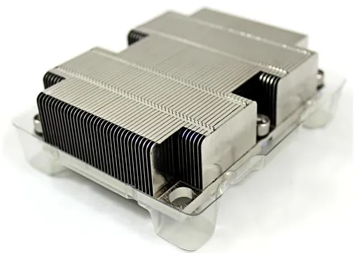
04 Bonded and Brazed Finned Heat Sinks
Bonded fin heat sinks are two-piece assemblies made from a base (extruded or machined) with grooves or slots, and fins that are bonded using a thermally conductive adhesive (usually epoxy resin or solder). To enhance structural integrity and thermal performance, these structures are sometimes brazed to reinforce both the thermal and mechanical bonds.
The fins are typically stamped from rolled stock or cut from thin sheet metal, while the base is usually extruded, die-cast, or machined. The base may also include additional heat integration features, such as embedded heat pipes or spreader plates, to enhance performance. Bonded heat sinks offer higher performance and larger surface areas in a smaller footprint by supporting more, longer fins with additional customization.
Advantages
• Compact, ideal for space-constrained applications
• High thermal performance
• Suitable for forced convection, with no limitation on airflow length
• Dense fin spacing
• High fin aspect ratio
• Easy integration, with high design flexibility
• Lower tooling costs
Disadvantages
• Not suitable for high-vibration or shock applications
• Cannot be used when thermal resistance is below 0.01°C/W.
05 Zippered Fin Heat Sinks
Zipper fin stacks are made from a series of individual stamped sheet metal fins that are interlocked and folded together using a zipper-like mechanism. The length and spacing of the fins vary depending on the stamping die. The fins can either be closed to form fin tubes or remain open depending on the application to allow multidirectional airflow. The fin stack is usually welded, brazed, or epoxied to the base or heat pipe to form a complete thermal component. The connection between the top and bottom fins enhances mechanical stability, making the heat sink more durable.
Zippered fin stacks offer highly flexible designs and are suitable for highly integrated solutions, using a wide range of technologies, from embedded and transport heat pipes and spreader plates to fans and large systems.
Advantages
• Compact, ideal for space-constrained applications
• High thermal performance
• Suitable for forced convection, with no limitation on airflow length
• Dense fin spacing
• High fin aspect ratio
• Easy integration, with high design flexibility
• Lower tooling costs
Disadvantages
• Some limitations for low thermal resistance requirements.
06 Folded Fins
Folded fins are made by folding a metal sheet to create various geometric shapes with larger surface areas. While these fins are used in a variety of technologies, including liquid cold plates, they are typically bonded or brazed to the base to form the heat sink.
Advantages
• Increased surface area and fin efficiency
• High heat flux density
• More material options
• Lightweight
Disadvantages
• Best when air is directly fed through the pipes to the heat sink
07 Die-Cast Heat Sinks
Die-cast heat sinks feature an integrated structure. They are primarily used in applications that are weight-sensitive, require excellent surface quality, or have highly complex geometries, produced in large volumes. These solutions are made by pouring a thermally conductive alloy into near-net-shape custom molds, followed by light machining and finishing to achieve the final product.
Advantages
• Ideal for high-volume, high-performance applications
• Suitable for complex geometries
• Low or no thermal resistance
• Lightweight
Disadvantages
• High initial tooling costs.