Beyond the Heat Pipe: When to Upgrade to Vapor Chamber Cooling
In the world of high-performance electronics, thermal bottlenecks are the enemy of speed. As a mechanical engineer or procurement manager, you’ve likely hit the “heat pipe wall.” You’re dealing with a high-flux component—an 800G optical transceiver, a high-end GPU, or a dense AI accelerator—and standard copper heat pipes simply aren’t spreading the heat fast enough. The result? Throttling, reduced component lifespan, and a design that can’t pass thermal validation.
When linear heat transfer isn’t enough, it’s time to move to 2D planar spreading. It’s time to upgrade to a Vapor Chamber.
This guide cuts through the marketing fluff to give you the engineering data you need: the performance thresholds, the design constraints, and the cost-benefit analysis of switching to vapor chamber technology.
What is a Vapor Chamber? (And Why Heat Pipes Aren't Enough)
Think of a vapor chamber as a “planar heat pipe.” While a standard heat pipe moves heat linearly (from Point A to Point B), a vapor chamber spreads heat in two dimensions (360 degrees) across its entire surface.
Inside the sealed copper vessel, a working fluid (typically de-ionized water) evaporates at the heat source. The vapor fills the vacuum-sealed chamber, condensing on cooler surfaces and releasing its latent heat. A sintered copper powder wick structure then draws the liquid back to the heat source via capillary action.
The “Spreading Resistance” Problem
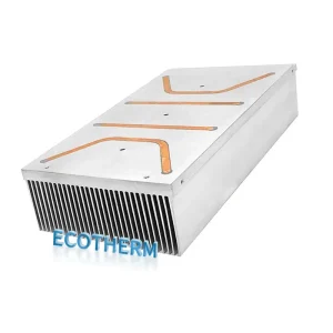
The primary reason engineers switch to vapor chambers is to conquer spreading resistance. If you have a small, high-intensity heat source (e.g., a $1cm^2$ ASIC generating 100W) attached to a large heatsink base, the heat struggles to reach the edges of the fins. A vapor chamber acts as a super-conductive base, instantly equalizing the temperature across the entire fin stack.
Send us your project to receive free project evaluation suggestions!
Vapor Chamber vs. Heat Pipe: The Decision Matrix
When should you approve the higher budget for a vapor chamber? It comes down to Power Density (W/cm2) and Geometry.
| Feature | Heat Pipe Assembly | Vapor Chamber (VC) Solution |
| Heat Transfer Direction | Linear (1D) | Planar / Multi-directional (2D) |
| Power Density Limit | Efficient up to ~30-40 W/cm² | Efficient > 50 W/cm² |
| Thermal Conductivity (keff) | ~3,000 – 8,000 W/m·K | > 5,000 – 20,000+ W/m·K |
| Min. Thickness | ~2.0mm (Flattened) | 0.4mm (Ultra-thin) |
| Design Flexibility | High (Can be bent) | Rigid (Formed by tooling) |
| Cost Multiplier | 1x (Baseline) | ~1.5x – 3x |
Key Takeaway: If your heat source power density exceeds 50 W/cm², or if you need to spread heat to a heatsink that is significantly larger than the heat source, a vapor chamber is often the only viable solution to keep junction temperatures (Tj) within safe limits.
Design Guidelines for Engineers
Integrating a vapor chamber isn’t as simple as swapping out a copper plate. To ensure reliability and manufacturability, you must adhere to specific design constraints.
1. Clamping Pressure Limits
One of the most common questions we receive from procurement teams is about durability. A standard vapor chamber is a hollow vessel. If you apply too much force, you risk collapsing the internal support pillars.
Standard Limit: Most commercial VCs can handle 60 PSI of clamping pressure.
High-Pressure Designs: For LGA sockets requiring higher force, we can engineer custom internal pillars to withstand 90+ PSI without deformation.
2. Flatness and CNC Machining Tolerances
The interface between your chip and the vapor chamber is critical. A warped surface creates air gaps, increasing thermal resistance ($R_{th}$).
Our factory utilizes precision CNC machining to finish the pedestal area of the vapor chamber. We maintain a flatness tolerance of 0.05mm per 25mm, ensuring optimal contact with the Thermal Interface Material (TIM).
3. Gravity and Orientation
Early vapor chambers struggled when working against gravity (e.g., inverted operation). However, our modern Sintered Powder Wick technology generates high capillary force, allowing our VCs to operate effectively in any orientation—vertical, horizontal, or inverted—with less than a 5% variance in thermal performance.
Manufacturing Excellence: Why Our Process Matters
Not all vapor chambers are created equal. In the B2B market, the difference lies in the bonding integrity and wick structure consistency.
One-Piece vs. Two-Piece Construction
For ultra-thin applications (like laptops or 1U server blades), we utilize a One-Piece Construction method.
The Benefit: By starting with a single copper tube and forming it into a chamber, we eliminate the need for a soldered edge seal. This “monolithic” approach reduces the risk of leakage over long-term thermal cycling—a critical factor for industrial and automotive clients.
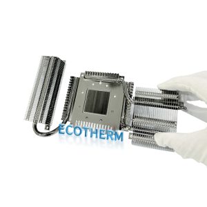
Integration with Fin Stacks
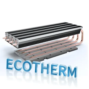
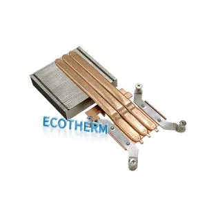
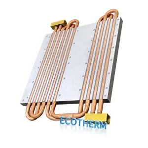
A vapor chamber alone cannot dissipate heat; it needs surface area. We specialize in soldering vapor chambers to Zipper Fins or Skived Fin stacks.
Process: We use high-conductivity solder paste and a controlled reflow process to ensure zero voids between the VC and the fins.
Result: A rugged, integrated thermal module ready for drop-in assembly.
Send us your project to receive free project evaluation suggestions!
Conclusion: Is a Vapor Chamber Worth the Investment?
If you are battling thermal throttling on a high-TDP component and traditional heat pipes are failing to move the heat fast enough, the answer is yes. A vapor chamber provides the lowest possible thermal resistance (Rth) for high-flux applications, effectively “de-densifying” the heat so your fins can do their job.
While the tooling cost is higher than simple extrusion or heat pipes, the performance gain—often reducing junction temperatures by 3-5°C or more—can be the difference between a failed prototype and a market-leading product.
Ready to validate your design?
Don’t guess with thermal simulations alone. [Contact our engineering team today] to request a DFM review or discuss our Custom Heat Sink Services. We can help you determine if a standard VC size works or if a custom-tooled solution is required.
FAQ: Frequently Asked Questions
1. What is the minimum thickness for a custom vapor chamber?
For standard industrial applications, we recommend a minimum thickness of 3.0mm to allow for a robust sintered wick structure and internal support columns. However, for mobile or ultra-compact designs, we can manufacture ultra-thin vapor chambers down to 0.4mm using specialized etched-wick manufacturing processes.
2. Can you repair a damaged vapor chamber?
No. A vapor chamber is a vacuum-sealed vessel. If the copper envelope is punctured or cracked, the vacuum is lost, and the working fluid will dry out, rendering the device useless (it effectively becomes a piece of solid copper). This is why our factory performs 100% Helium Leak Testing and thermal performance checks before shipping to ensure every unit is hermetically sealed.
3. How does a Vapor Chamber compare to a solid copper heat spreader?
A vapor chamber is significantly lighter and more conductive than solid copper. While copper has a thermal conductivity of ~400 W/m·K, a vapor chamber has an effective conductivity (Keff) of 5,000 to over 20,000 W/m·K depending on the power load. This means it spreads heat 10x to 50x faster than solid copper, eliminating hotspots much more effectively.