Cold Plate Cooling: How It Works and How to Select a Plate
What Is Cold Plate Cooling?
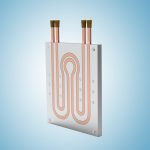
Cold plate cooling is a highly efficient thermal management method used to dissipate heat from high-power electronic components. It works by mounting heat-generating devices directly onto a thermally conductive metal plate, which contains internal channels for a liquid coolant to circulate and absorb the heat.
Cold plate cooling removes heat from a component through a metal plate containing liquid passages or embedded tubing. The component transfers heat into the plate through its mounting interface, and circulating coolant carries that heat away. A liquid cold plate is therefore a heat-transfer component—not a complete cooling system.
This guide focuses on pumped, single-phase cooling, in which the coolant remains liquid rather than boiling inside the plate.
How Does Cold Plate Cooling Work?
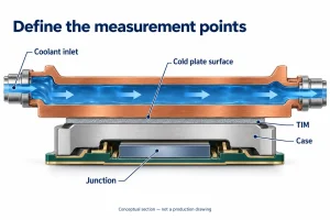
The cooling process relies on a combination of conduction and forced convection. Heat first transfers from the component’s surface, through a Thermal Interface Material (TIM), and into the metal body of the cold plate.
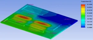
As the liquid coolant—typically water, a glycol-water mixture, or a specialized dielectric fluid—flows through the internal channels, it absorbs this thermal energy. The heated fluid then exits the cold plate and travels to a heat exchanger or radiator within the broader liquid cooling loop, rejecting the heat into the ambient air or facility water before returning to the plate.
When Is Cold Plate Cooling Appropriate?
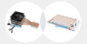
Air cooling is usually sufficient for systems with low heat flux, ample space, and no existing liquid loop. The shift to cold plate cooling becomes necessary when thermal demands exceed what convection can handle.
The deciding factor isn’t just total wattage—it’s heat density. When components generate concentrated heat that overwhelms traditional finned heat sinks, liquid cooling provides the required thermal capacity. Cold plates are also the practical choice when tight enclosures restrict airflow, leaving no room for bulky high-CFM fans, or when high ambient temperatures render air cooling ineffective.
Keep in mind that while liquid cooling reduces the need for loud local fans, it isn’t inherently silent or zero-energy. The broader system still relies on pumps and external heat exchangers, and surrounding board components may still require baseline airflow.
Common Cold Plate Designs
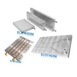
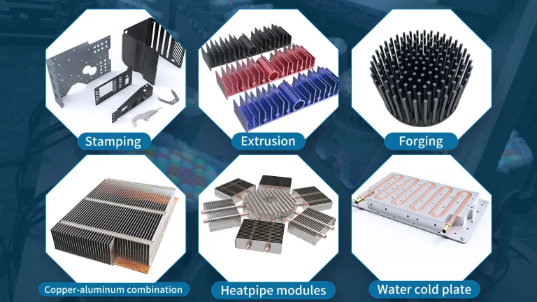
The internal geometry and manufacturing method of a cold plate dictate its thermal performance and pressure drop.
Manufacturing methods and channel layouts describe different aspects of a cold plate. Vacuum brazing and friction stir welding are joining processes; serpentine and parallel describe fluid routing. “GPU cold plate” describes an application, not a manufacturing method.
| Construction | Why consider it? | Main limitation to review |
|---|---|---|
| Tube embedded | A tube fitted into a grooved metal base provides a defined coolant path beneath the mounting area | Tube routing, spacing, and tube-to-plate contact affect heat spreading and hotspot temperature |
| Gun drilled | Straight or intersecting bores form passages within a solid plate | Drilling access, passage placement, and the integrity of plugged closures constrain the design |
| Vacuum brazed | Joining a base, cover, and suitable internal features allows enclosed passages and compact assemblies | Joint preparation, braze quality, internal cleanliness, and post-process flatness require control |
| Friction stir welded | A solid-state weld closes a machined base with a cover | Tool access, weld-path clearance, and finishing requirements must be considered |
Channel layout introduces further trade-offs. A serpentine passage directs coolant along one continuous route, but coolant warms along that route and a long passage can increase pressure loss. Parallel passages divide the flow; distribution depends on manifold design and individual passage resistance.
These are starting points for design review, not a ranking of technologies. No construction method is automatically the most effective or leak-proof.
How to Select a Cold Plate
Define the heat load and temperature limits
Start with the heat that must enter the cold plate, rather than the equipment’s total electrical input. Record each component’s heat dissipation, contact footprint, location, peak load, and duty cycle. Two assemblies with the same total heat load can need different plates if one concentrates heat into a much smaller area.
Identify exactly where the temperature limit applies: semiconductor junction, device case, or cold-plate mounting surface. These temperatures are not interchangeable. The available temperature margin must accommodate the device package, TIM, heat spreading, plate-to-coolant transfer, and coolant warming.
Use the highest expected coolant inlet temperature for the relevant operating condition. When comparing thermal-resistance data, check the heater footprint, coolant, flow, temperature reference, and measurement location. An average plate value does not establish the temperature of an individual hotspot. Eaton’s cold-plate selection guide illustrates why these test conditions matter.
Estimate flow, then check pressure drop
For steady single-phase operation, the coolant heat balance is:
Q = ṁ × cₚ × (T_out − T_in)
Here, Q is heat transferred to the coolant in watts, ṁ is mass flow in kg/s, and cₚ is specific heat in J/(kg·K). The temperature difference is the coolant rise—not the difference between the component and coolant.
For a step-by-step explanation of units and fluid properties, the guide to calculating cold plate flow rate develops this relationship further.
Illustrative calculation—not an Ecotherm test or customer result
Assume 600 W enters the coolant at steady state, with negligible heat loss elsewhere. Water enters at 25°C, and the selected allowable coolant rise is 5 K. Using approximate constant properties near 25°C—cₚ = 4,180 J/(kg·K) and density = 997 kg/m³—gives:
- Mass flow = 600 ÷ (4,180 × 5) ≈ 0.0287 kg/s
- Volumetric flow = (0.0287 ÷ 997) × 60,000 ≈ 1.73 L/min
- Estimated outlet temperature = 25 + 5 = 30°C
The rounded water properties are consistent with the reference values at 25°C and 0.1 MPa in this NIST-hosted water-property paper, Table 8. The 5 K rise is an example assumption, not a general design target.
This calculation establishes coolant heat-carrying capacity only. It does not prove that the mounting surface stays below its limit or that the pump can deliver the required flow.
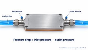
Check the operating point against the pump curve and complete loop resistance, including the plate, fittings, hoses, filters, and heat exchanger. Use properties for the actual coolant and operating temperature. Cold-plate pressure drop is also different from its allowable working pressure; both require review.
Match the fluid, mounting interface, and available space
Review all wetted materials, including tubing, fittings, seals, and other loop components—not just the plate base. Neither copper nor aluminum is universally corrosion-proof. Coolant chemistry, inhibitors, material combinations, and temperature determine compatibility. Eaton’s corrosion guidance explains why corrosion and deposits can compromise both heat transfer and leak integrity.
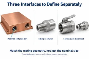
Confirm flatness, surface finish, TIM thickness, and clamping requirements. Poor contact can undermine an otherwise suitable design. Also check the mounting-hole pattern, plate thickness, component clearances, port standards and orientation, hose-bend space, service access, and any electrical-isolation requirement.
An initial geometry comparison can use the cold plate calculator, provided its assumptions fit the concept. Its simplified model is for preliminary screening; uniform heat input and equal channel flow do not represent every real assembly. Hotspots, contact resistance, and transient loads still require separate assessment.
When standard geometry cannot accommodate the heat-source map, mounting pattern, or connections, custom liquid cold plates allow these requirements to be considered together. Prototype validation should then check the agreed thermal, hydraulic, and mechanical conditions before design release.
Reliability and Maintenance
Cold-plate reliability starts with the body, joints, ports, internal cleanliness, and mounting interface. Leak testing and proof-pressure testing address different requirements; test methods, acceptance criteria, and documentation should be agreed for the application.
The complete loop has additional service needs. Hoses, seals, filters, pumps, coolant, and external heat-rejection equipment require attention even when the plate itself has no moving parts.
Follow the equipment manufacturer’s procedures and coolant supplier’s requirements for inspections, fluid analysis, cleaning, and replacement. There is no universal coolant-change interval. For single-phase liquid-cooled racks, the Open Compute Project’s fluid guidelines link maintenance to the treatment plan, supplier guidance, and fluid condition.
Record temperatures, flow, and pressure drop under comparable operating conditions. Deteriorating performance may reflect contamination, corrosion, trapped air, reduced flow, or degraded contact. Investigate the cause before simply increasing pump speed or replacing coolant.
Standard vs. Custom Solutions
Standard, off-the-shelf cold plates are useful for rapid prototyping or accommodating standardized component footprints. However, when the heat-source layout, mounting hole locations, or available space do not match an off-the-shelf design, custom liquid cold plates allow those requirements to be reviewed together. Customization ensures that internal flow paths are routed exactly where they are needed, optimizing pressure drop and eliminating localized hot spots.
FAQ
Can a cold plate cool below ambient temperature?
Only if the external cooling arrangement supplies sufficiently cold coolant; the plate does not generate refrigeration. If a surface falls below the local dew point, condensation becomes possible. Sub-ambient operation therefore needs a condensation-control strategy based on local temperature and humidity, potentially including coolant-temperature control and insulation. This is a system-design issue, not an inherent cold-plate benefit.
Is a cold plate the same as a vapor chamber?
No. The pumped, single-phase cold plate described here exchanges heat with circulating liquid in an external loop. A vapor chamber is a sealed, passive heat spreader that uses internal evaporation and condensation. It redistributes heat but still needs a path for rejecting that heat outside the chamber.
Have a project to discuss? Share any available drawings, heat-load estimates, coolant conditions, installation space, or expected quantity through Ecotherm’s custom cold plate enquiry page.