Cold Plate Manufacturing Process: From Drawing Review to Sample Approval
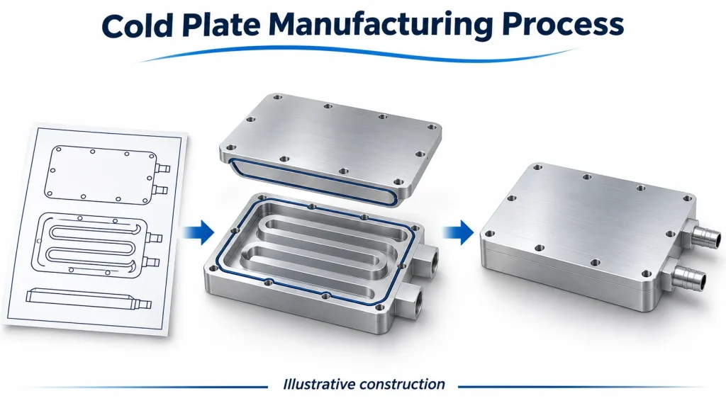
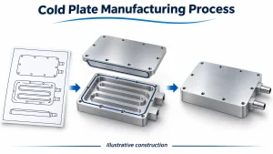
The cold plate manufacturing process starts with a controlled drawing, forms the coolant path, completes the required assembly and finishing operations, and verifies the finished part before sample approval. The sequence depends on the construction: an embedded tube, a welded cover, a brazed assembly, and a drilled block do not follow the same route.
For engineers and buyers, the useful questions are what happens at each stage, which features become inaccessible, and what evidence accompanies the sample. This guide follows four representative metal cold plate constructions used in single-phase electronics cooling. Surface treatment is included where specified; applying a coating is not a universal step.
1. Confirm the Drawing and Manufacturing Route
Before cutting material, identify the drawing revision, materials, critical dimensions, and agreed acceptance requirements. Record approved deviations separately so the sample is not built from an untracked mixture of emails and older files.
Distinguish the material of the supporting plate from the materials exposed to coolant. In an embedded-tube design, for example, the aluminum base and copper or stainless-steel tube have different roles. For a base-and-cover design, the base, cover, joining materials, and supplied connections all need consideration.
Review the channel layout, port positions, mounting faces, and sealing features with the proposed manufacturing route. If a tube bend, cover joint, or machining feature must change, approve that change before it enters the sample build. A manufacturer’s feasibility suggestion should become a documented revision or concession, rather than an invisible modification.
For build-to-print work, establish which requirements are already fixed. Where design support is needed, identify the open decisions and who will approve them. This keeps manufacturing review focused on producing the intended part.
2. Build the Flow Path Using the Chosen Cold Plate Construction
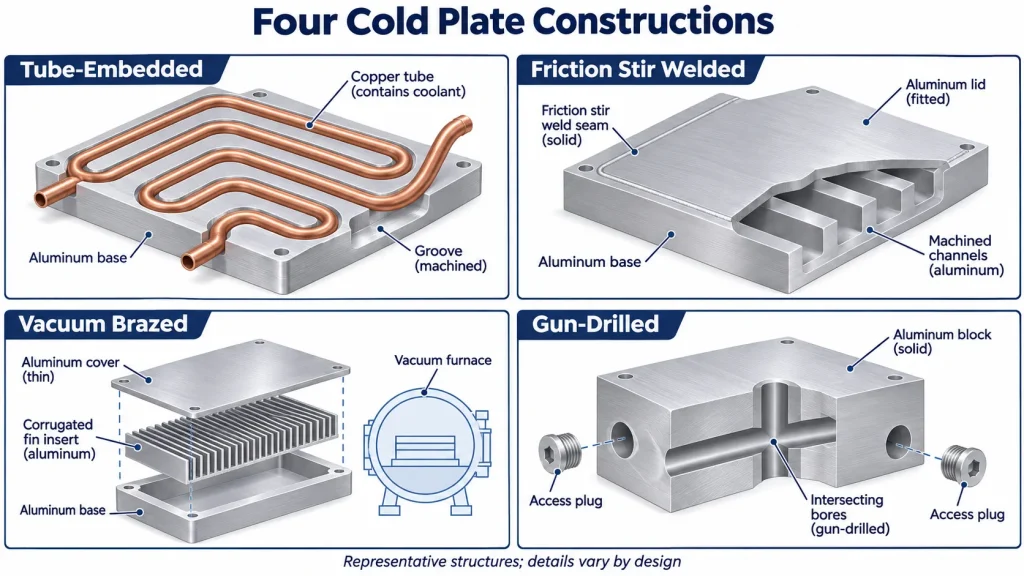
The main production differences lie in forming and containing the coolant path. The following routes are representative examples, not an exhaustive list. A “microchannel” describes internal geometry; it does not identify one universal joining method.
Prepare the specified stock, tube, cover, or inserts for the chosen route, with the material identity traceable to the order. Inspect accessible features before the next operation hides them; waiting until the finished sample may make direct inspection impossible.
Tube-embedded cold plates
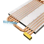
A typical route is to prepare grooves in the base, bend the tube to the required path, and press or mechanically retain it in the plate. Some designs use a thermally conductive compound at the tube-to-plate interface; others use a mechanical joint without it. Boyd’s Hi-Contact and pressed-tube datasheets illustrate these different approaches.
Coolant remains inside the tube. The tube-to-base interface transfers heat, while the tube wall and its connections contain the fluid. Check tube position, bends, and seating before later operations conceal access. Embedding the tube does not remove the need to verify its fluid boundary.
Friction stir welded cold plates
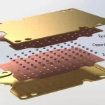
Channels may be machined into the base or provided by a suitable extruded section, depending on the design. Prepare the cover and joint features, inspect accessible internal features, and remove machining debris before closing the assembly. The parts are then supported and clamped for welding.
A rotating tool softens and stirs material along the joint to form a solid-state weld. It does not join the plate by melting a brazing filler. TWI’s explanation of friction stir welding tools describes the backing and clamping involved. Tool access, joint support, and weld completion details belong in the manufacturing review.
Vacuum brazed cold plates
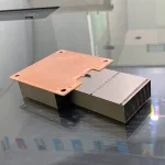
The base, cover, and any internal inserts are made and cleaned for the specified brazing process. They are assembled with the required brazing filler arrangement, held in position, and processed through a controlled furnace cycle. The filler melts to form the joints; the base components are not intentionally melted.
Before enclosure, inspect features such as insert placement and passage openings where required by the inspection plan. The subsequent checks must address the joined assembly, including its final dimensions and fluid boundary. A clean-looking exterior does not establish the condition of an internal joint.
Vacuum brazed cold plates
Deep-hole drilling creates straight passages in a solid block. Intersecting bores can connect those passages into the specified flow route. Manufacturing access openings are then closed using the designed plugs or caps.
This construction can avoid a broad base-to-cover joint, but it still contains closures and fluid ports. Passage position, intersections, debris removal, and closure details need attention before the part is released. Inspection and leak testing must include the relevant closures rather than treating a solid starting block as proof of tightness.
3. Complete Machining, Cleaning, and Specified Surface Treatment
Depending on the construction, mounting faces, holes, ports, or other features may need machining after joining or assembly. Establish the required finished condition on the drawing. An intermediate dimensional check does not demonstrate compliance after later operations have changed the part.
Deburring and cleaning can occur at several stages, especially before passages become inaccessible. Final preparation must also account for subsequent testing, handling, and the agreed shipping condition.
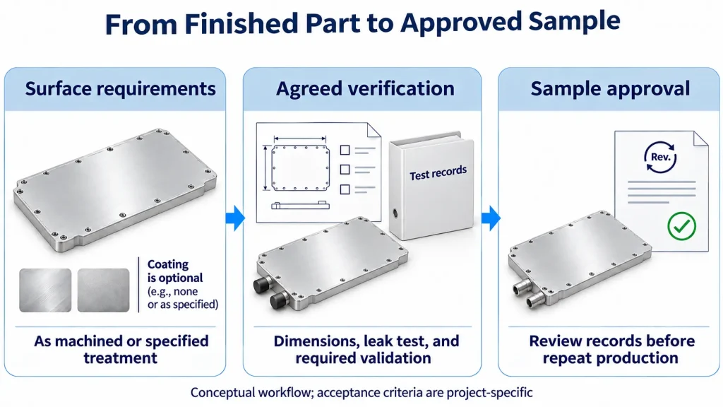
Surface treatment is conditional. A cold plate may be supplied as machined or with a specified finish. For example, the Hi-Contact datasheet above lists an unfinished standard product. Anodizing or plating should therefore follow material, coolant, electrical, corrosion, and interface requirements rather than being added automatically.
Identify the treated surfaces, any masking or exclusions, and the acceptance stage. Review the external component-contact face, sealing faces, threads, and internal wetted surfaces separately. An exterior treatment does not establish protection inside the coolant path. Added coatings can also affect dimensions and interfaces, so the drawing should resolve how these features are accepted.
There is no single finishing order for every cold plate. Agree the sequence for the actual construction, including how later operations will be checked.
4. Verify Leak Tightness and the Finished Sample
Leak tightness is a common acceptance concern across these constructions, but the test method and conditions must suit the supplied part. Define the tested boundary: the plate alone, the plate with installed fittings, or a larger assembly. Record which interfaces are sealed by the fixture. A body test does not verify hoses or fittings installed afterward.
An early leak check may help identify manufacturing defects before more work is added. The inspection plan should also define the final verification or retest needed after operations that could affect the pressure boundary. Neither “always before coating” nor “always after coating” is a complete rule.
Agree on the method, test medium, pressure conditions, stabilization and measurement times, acceptance criterion and units, and recorded result. Pressure-decay testing and tracer-gas testing have different capabilities. Temperature changes, for example, can influence pressure-decay results independently of leakage, as INFICON’s heat-exchanger testing guidance explains.
Keep three questions separate:
- Leak testing: Does the defined fluid boundary meet the agreed leakage requirement?
- Proof-pressure verification: Does the part withstand the specified pressure without unacceptable damage, deformation, or leakage?
- Thermal and hydraulic testing: Does it meet the required cooling and flow performance under stated conditions?
These distinctions are consistent with the separate mechanical, performance, and reliability assessments in the OCP cold plate development and qualification paper. Product qualification and routine shipment checks need an agreed scope; they are not automatically identical test programs.
5. Approve the Sample Before Repeat Production
Sample approval should connect a physical part to its drawing, manufacturing route, and inspection evidence. Confirm the sample identity and revision, approved deviations, final surface condition, and supplied connection configuration.
Review the applicable dimensional results, leak-test records, and any additional validation required by the project. A successful fit check alone does not establish leak tightness or cooling performance. Record unresolved items and the decision needed before production release.
The accepted sample and its records then provide a reference for repeat orders. If the material, geometry, joining route, or connections change later, review the impact and agree on any necessary revalidation. This does not mean every change requires the entire qualification program to be repeated; it means the change receives an explicit engineering decision.
For a custom liquid cold plate project, send Ecotherm your current drawing and a brief application description. Include known coolant or test requirements and the sample quantity you need. If some details remain open, identify them so the manufacturing route and approval requirements can be discussed together.
Related guides for your drawing and sample review
Cold Plate Flatness for IGBT Modules: Drawing Guide — Define the mounting areas, final surface condition, and inspection requirements for an IGBT project.
Cold Plate Cleanliness for AI Servers: Buyer’s Guide — Specify the internal delivery condition, supporting evidence, and protection through shipment.
Cold Plate Ports and Fittings for AI Servers — Resolve connection and sealing details when defining the supplied and tested assembly.