Cold Plate Ports and Fittings for AI Servers: What to Specify on Your Drawing
Specify a cold plate connection by its complete mating interface—not just a thread size. The drawing needs to define the port, the fitting that enters it, the seal and the space required to install and service the assembled connection.
In an AI server cold plate assembly, these details connect the manufactured plate to the rest of the cooling loop. A bare plate may fit the available space while its elbow, hose termination or service coupling does not. A thread may match while the sealing geometry does not.
This guide explains what to resolve with the cold plate manufacturer and fitting supplier before machining. It does not prescribe one connector family or port size for every AI server.
Specify the Port Interface, Not Just the Thread Size
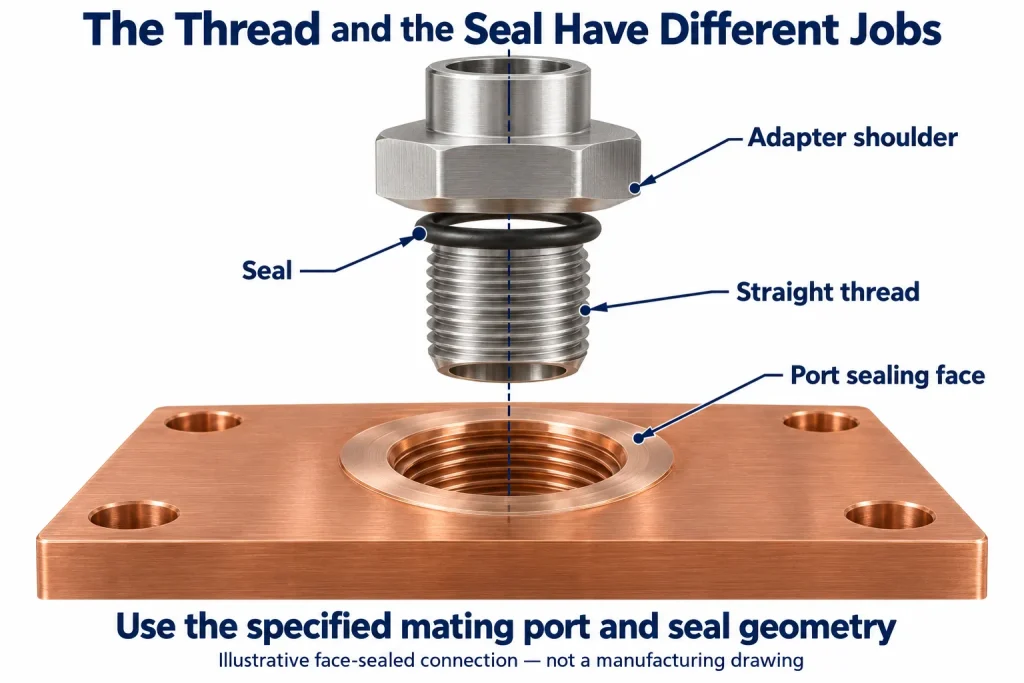
A thread designation is a starting point, not a complete interface specification. Swagelok distinguishes a thread standard, which describes features such as form, pitch and diameter, from an end connection standard, which also defines components and sealing geometry. Matching threads alone do not establish a compatible seal. See its Thread and End Connection Identification Guide.
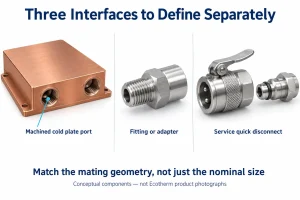
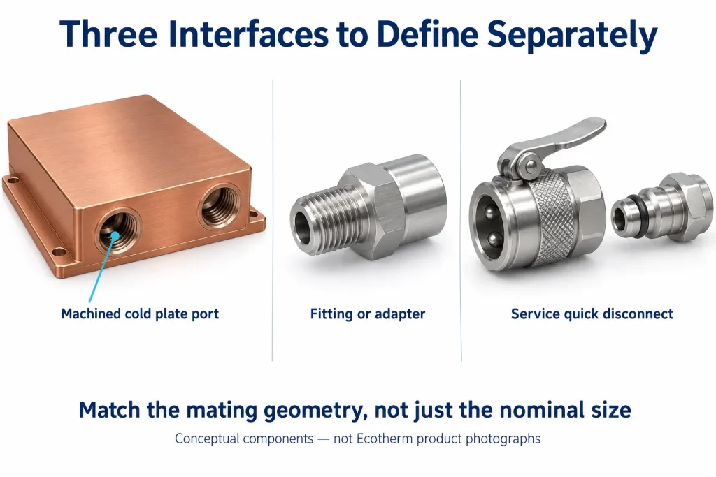
Keep three items distinct:
– **Machined cold plate port:** The opening and associated features produced in the plate.
– **Fitting or adapter:** The component connecting that port to a hose, tube or other component.
– **Service quick disconnect:** A separable connection that may sit elsewhere in the assembly or attach through a separately specified port interface.
Identifying a quick disconnect model does not automatically define the cold plate machining. Obtain the drawing for its actual termination, or for the adapter between it and the plate.
The drawing should identify where the seal forms. In parallel-threaded port connections, the threads provide retention; sealing depends on the specified mating geometry. O-ring boss and face-sealed arrangements are not interchangeable descriptions. Parker’s Port End Assembly Guide illustrates the different arrangements.
Before releasing the port detail, confirm:
| Drawing item | Decision to resolve |
|---|---|
| Mating component | Complete fitting part number and supplier drawing revision, or a complete interface standard |
| Seal interface | Seal location, seating geometry, specified finish and responsibility for supplying the seal |
| Thread and engagement | Thread designation, required engagement and manufacturing review of surrounding material |
| Flow opening | Required passage through the connection, separately from its nominal thread designation |
Do not treat BSPP and NPT as substitutes because their nominal labels look similar. Likewise, a nominal thread size is not the physical flow bore. Ask both suppliers to confirm the same mating detail instead of independently choosing a seal arrangement.
Place Ports Around the Assembled Routing and Service Envelope
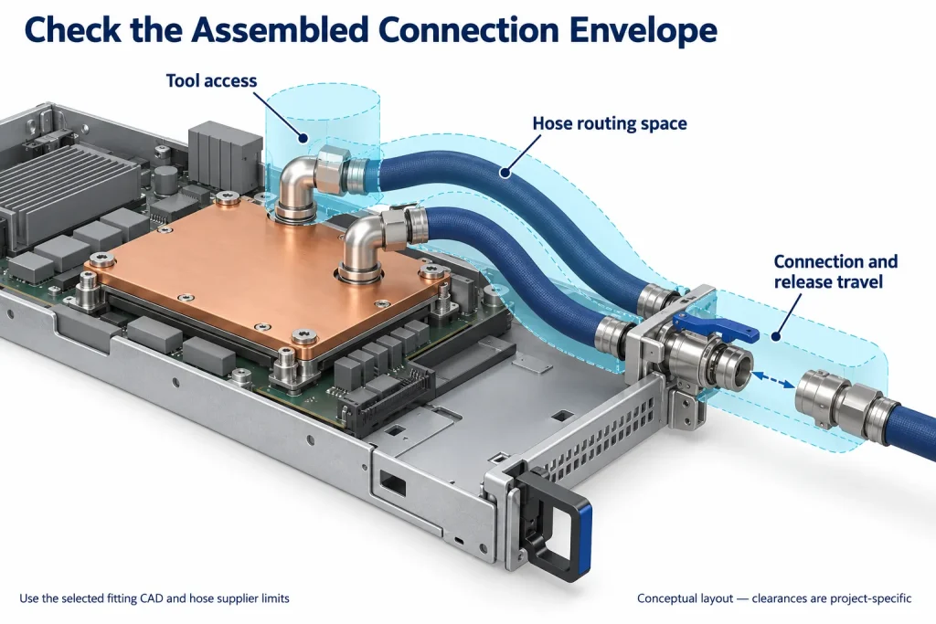
Locate ports with the selected fittings and hoses installed in the server assembly. Compare top and side entry against available height, hose routing and service sequence. Either arrangement can work; the bare cold plate footprint does not decide the issue.
Use the hose supplier’s minimum bend radius for the actual hose style and size. Construction, wall thickness and reinforcement affect that limit. A bend that is too tight can kink the hose, restrict flow and cause early failure. An elbow may reduce the bend demanded of the hose, but routing must also avoid sharp edges and abrasive contact. OCP’s hose and manual coupling guidance discusses these considerations.
Build the clearance model from the selected fitting supplier’s CAD and dimensional drawing. Include the adapter, elbow, hose termination and coupling where applicable. State which dimensions apply to the bare plate and which apply after assembly. Check the tolerance stack at nearby boards, busbars, covers and neighboring modules.
Review three envelopes rather than one:
1. **Installed envelope:** The space occupied by the complete connection and supported hose route.
2. **Assembly envelope:** Room to reach the wrench flats, move the tool and install surrounding parts in the intended sequence.
3. **Service envelope:** Room for fingers, latch or sleeve actuation, and the travel needed to separate mating coupling halves.
Define elbow orientation relative to a drawing datum and use the fitting supplier’s approved adjustment method. Do not plan to back off a fixed fitting to aim the hose. Where assembly access depends on installing one component before another, record that sequence.
Review service motion with the module in its intended maintenance position. Place supports so the hose remains controlled without forcing a tighter bend. The technician should be able to handle the connector directly rather than pulling the hose as a lever against the port.
Check the Complete Connection for Flow and Compatibility
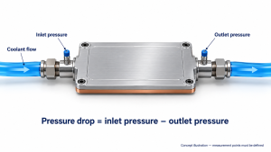
Define whether the pressure-drop allowance covers the plate alone or includes adapters, hoses and both halves of each quick disconnect. Multiple connections contribute to the total pressure loss. A port thread designation does not describe all restrictions inside the assembled flow path.
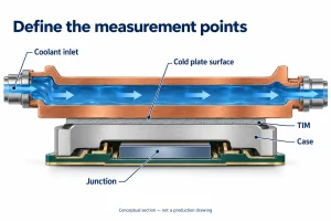
Compare options at the same flow rate, coolant temperature and composition. Keep allowable working pressure separate from pressure drop: one describes a pressure limit under specified conditions; the other describes resistance to flow. Mark inlet and outlet measurement locations so a plate-only result cannot be mistaken for the performance of a fully connected assembly.
For quick disconnects, identify the mating body and insert, including their end terminations. CPC’s Everis LQ2 documentation distinguishes these components, lists different termination options and presents water-flow data. Use supplier data for the documented configuration, then establish the evidence needed for the project’s coolant and assembly. A shared product-family name does not demonstrate identical performance for every termination or mating combination.
Compatibility review should cover all wetted materials: plate substrate and coatings, adapters, hose liner, coupling components and seals. Specify the coolant blend, concentration, additive package and temperature range. Request evidence for that combination rather than choosing EPDM or FKM on the assumption that one is always better. Record material restrictions and unresolved combinations.
Before approving the connection, freeze the qualification boundary. List the components and mating pairs included, fluid and temperature conditions, and acceptance criteria for pressure drop and leakage. Identify where component data still requires assembly-level confirmation.
Avoid accepting a broad “non-spill” description as a complete service requirement. Obtain the selected coupling’s documented connection and disconnection conditions and assess them against the equipment’s actual service procedure.
Release a Drawing Package That Both Suppliers Can Use
State whether the order covers a bare machined plate, a plate with fittings installed or another defined condition. A fitting shown in CAD does not establish who purchases, supplies or installs it.
For a firm release, keep the handover package compact:
- Released 2D drawing: Identify the revision, port and inspection requirements, and delivered condition. Reference the selected mating component wherever it governs machining.
- Matching 3D assembly: Include the selected fitting geometry and revision. Identify simplified CAD features that must not govern manufacturing or inspection.
- Responsibility statement: Assign fitting procurement, seal supply, installation and assembly leak testing. Define the tested configuration, acceptance criteria and report owner.
- Change control: Review substitutions before approval. A replacement fitting can alter the seal, installed envelope or hydraulic performance even if its nominal thread matches.
Keep dimensional acceptance separate from assembly acceptance. Specified thread-gage and dimensional checks assess manufactured features; they do not establish that the completed joint is leak-tight. Follow the selected fitting manufacturer’s assembly instructions, including checks for burrs or damage and the specified seals and compatible lubricants.
Keep the connection package alongside the cold plate design requirements. The port detail must remain consistent with the plate material, internal passage and manufacturing route—not become a late addition that forces an unreviewed geometry change.
An initial RFQ can be lighter than the production-release package. Start with the drawing or layout you have, the chosen fitting if available, the coolant specification and required quantities. Mark unresolved selections so the quotation can identify its assumptions. Add the heat-source map and operating conditions if thermal design review is also needed.
Send that starting package for an Ecotherm custom cold plate manufacturing review. Use the discussion to resolve port machining and assembly requirements, and confirm who supplies the fittings and what inspection evidence can be provided before production.