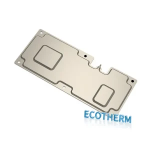
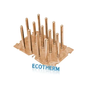
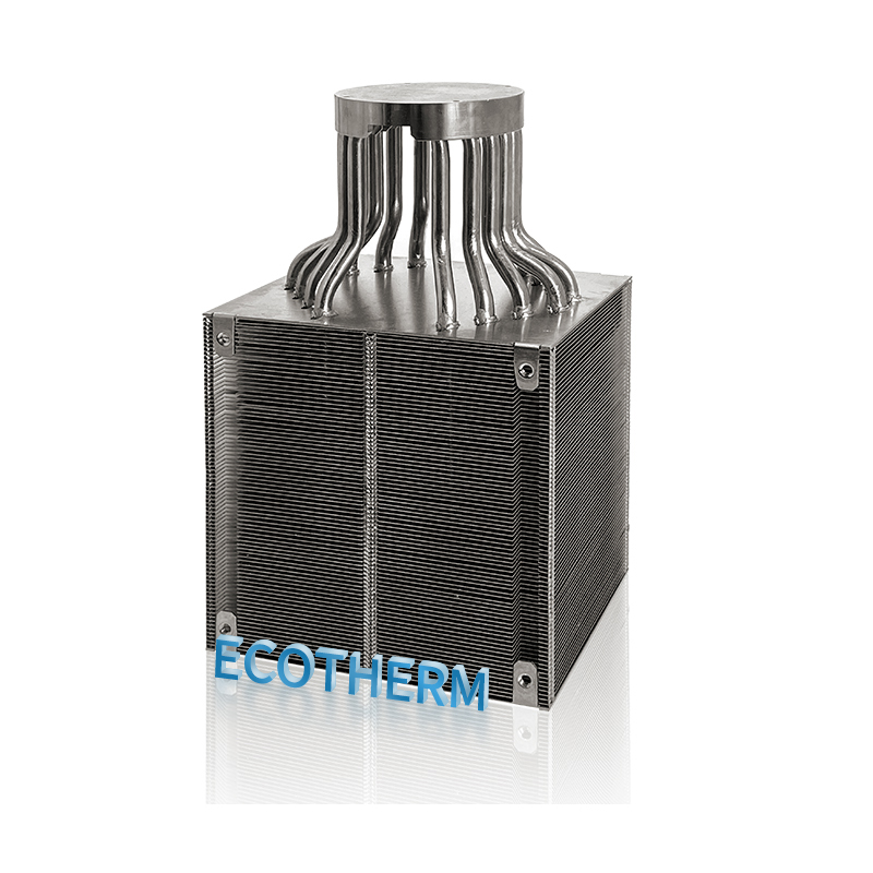
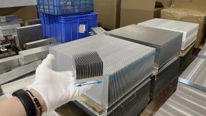
Skived heat sinks are made by precision skiving of metal profiles, usually copper or aluminum, at specific angles and intervals to create high-density fins perpendicular to the base. This process results in thinner, denser fins, significantly increasing the surface area for improved heat dissipation.
These heat sinks are typically made from copper or aluminum, known for their excellent thermal conductivity—copper at 401 W/m·K and aluminum at 237 W/m·K. The skiving method minimizes thermal resistance when compared to conventional welding or pin-fin structures, improving heat dissipation. Furthermore, supplementary post-processing methods, such as incorporating copper tubes or utilizing surface treatments, can enhance cooling effectiveness even more.
Skived heat sinks are often considered a type of heat sink that can be customized to meet specific requirements, but they also come in standard versions suitable for various applications.Thanks to their superior thermal conductivity, compact design, and durability, skived heat sinks are ideal for a wide range of high-efficiency cooling applications. Custom heat sinks can be designed to fit unique configurations, ensuring optimal cooling performance in specialized devices. With increasing market demand, new designs such as wave-shaped and double-sided skived heat sinks are also available, offering even greater flexibility and cooling power.
Distance from the first and last fins to the substrate edge ≥ 50% of the fin spacing
Tolerance of ±1 fin for 40 fins or more
Cross-Cutting
Fins longer than 300mm require additional transverse cutting to suppress surface waviness
6.Cross-Cut Implementation
For extended fin configurations, the implementation of cross-cutting is advised to mitigate surface curvature deviations, suppress waviness formation, and enhance turbulent airflow dynamics.
7.Fin Removal for Component Clearance
To accommodate attachment hardware (e.g., fasteners or auxiliary components), machined features should be fabricated as square or rectangular geometries with radiused corner profiles. Clearance dimensions must correlate with the mechanical specifications of mating components (e.g., screw head diameter) to eliminate spatial interference risks. Final clearance parameters—including corner radii and dimensional tolerances—are determined through engineering analysis to guarantee manufacturability and milling precision. Post-machining, residual steps measuring approximately 0.2 mm will persist in fin-removal zones due to material subtraction during CNC operations.
WHY choose Customized Heat Sink?
Custom Sizes Up to 3m x 90cm
Specialized Surface Finishes
Double-Sided & Wavy Skived Fin Options
100% Quality Inspection
Explore Our Range of Tailored High-Power Designs
Customize for Unique Heat Sink Solutions
Dimension and Shape
Customers can specify the dimensions (length, width, height) and shape (e.g., rectangular, circular, or custom shapes) based on their application requirements.
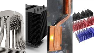
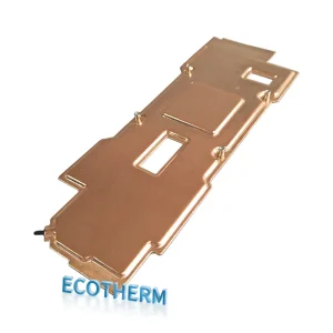
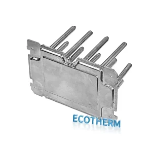
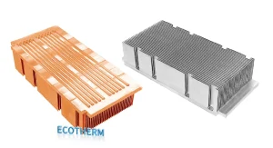
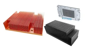
Surface Treatment
Options for different materials, such as aluminum, copper, or composite materials, can be provided to meet thermal conductivity, weight, and cost considerations.
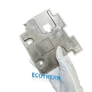
Material Selection
Various surface treatment options can be offered, such as anodizing, coating, or nickel plating, to enhance corrosion resistance and aesthetics.
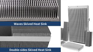
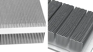
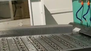
Thermal Performance
The design of the heat sink can be customized regarding the number and shape of fins to optimize heat transfer and dissipation efficiency.
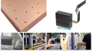
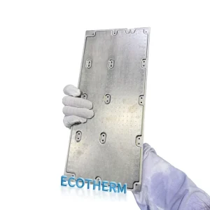
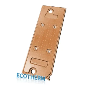
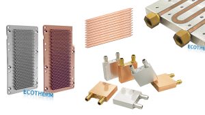
Mounting Options
Customization for mounting methods (such as screw mounting, clamps, or welding) and interface design can be provided to fit specific installation requirements.
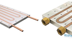
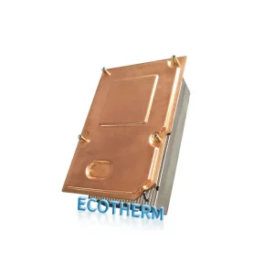
Additional Features
Options for integrating additional functionalities, such as fan incorporation, temperature sensor placement, or fluid cooling channels, can enhance the thermal management capabilities.