Heat Sink Structural Design — Forced Convection Heat Sink Design
Heat Sink Structural Design — Forced Convection Heat Sink Design
Increase Thermal Conductivity Coefficient
(1) Increase Airflow Velocity
This is a direct method that can be achieved by using a fan with a higher wind speed.
(2) Flat Fin Design with Crosscuts
By cutting flat fins into multiple shorter sections, the heat sink surface area is reduced, but the thermal conductivity coefficient increases, and pressure is also increased. This design is more suitable when the airflow direction is unpredictable (e.g., heat sinks on motorcycles).
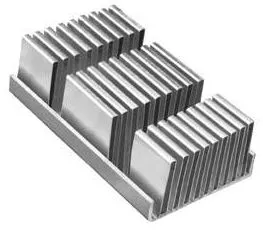
Crosscut Heat Sink
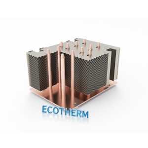
(3) Needle-Shaped Fin Design
Needle-shaped fin heat sinks have the advantages of being lightweight and compact, as well as having higher volumetric efficiency. More importantly, they have an isotropic structure, making them suitable for forced convection heat sinks, as shown in Figure 9. The fins can be in rectangular, round, or oval shapes. Rectangular fins are made from extruded aluminum, while round fins are forged or cast. Oval or droplet-shaped fins have higher thermal conductivity but are more difficult to form.
(4) Impulsive Flow Cooling
This method uses airflow directed from the top to the bottom of the fins, which increases thermal conductivity. However, attention must be given to the direction of the airflow in coordination with the overall design.
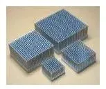
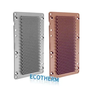
Needle-fin heat sink
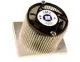
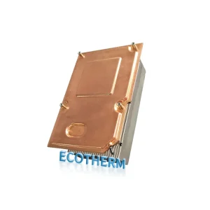
Radiating fin heat sink
Radiating Fin Heat Sink
For the common design where the fan is placed above the heat sink for downward blowing, a more precise design is needed to accommodate the fan’s characteristics. Axial fans have a rotational effect, and since air is not easily directed at the fan axis, many heat sinks are designed in a radial pattern, as shown in Figure 10. Some heat sinks are designed with fins of varying lengths or curved shapes at the top to guide airflow.
Another approach is to use a side-blowing design. In general, side-blowing heat sinks allow the airflow to pass through the fins with less resistance, making them more effective for high-density, tall fins. The design often includes a cover at the top to prevent airflow bypass (bypass effect). Side-blowing designs tend to be more effective than downward-blowing designs for certain applications.