IGBT Power Module Heat Dissipation Technology
1.Passive Cooling
1.1 Fin Heat Dissipation Technology
The heat generated by the IGBT power module is dissipated through the heat sink fins by natural convection.
According to the Newton’s cooling formula for convective heat transfer, the heat dissipation rate for a contact surface with an area of A is given by:
Where:
Ø is the heat dissipation rate,
A is the heat dissipation area,
h is the convective heat transfer coefficient,
Δt is the temperature difference.
It can be seen that the heat dissipation effect can be enhanced by increasing the area A and the heat transfer coefficient h.
When the IGBT power module undergoes natural convection heat dissipation, the forces influencing the heat dissipation flow field of the fins are mainly divided into two categories: natural convection flow field driving force and fin array resistance.
Figure 1 shows two different fin arrangements as examples.
Relevant parameters such as fin spacing, structure, height, and orientation all affect the heat dissipation performance of the fins. Charles et al. constructed fins of different shapes, including trapezoidal, inverted trapezoidal, and rectangular.
Experimental results showed that the heat transfer coefficient of the inverted trapezoidal fins was 25% higher than that of trapezoidal fins and 10% higher than that of rectangular fins. The design and optimization of horizontal fin heat sinks focus on the fin thickness, height, and spacing, typically aiming to use the minimum material while dissipating the maximum heat.
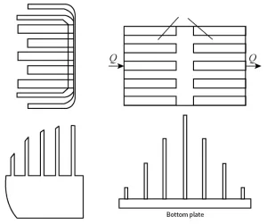
Figure 1: Different Fin Arrangements for Heat Sinks
The commonly used materials for heat sinks are copper and aluminum alloys, which are manufactured through processes such as die-casting and extrusion.
Generally, the material of choice for heat sinks is aluminum alloy, as it not only has good thermal conductivity but also offers a high cost-performance ratio. Chang et al. developed paraffin/graphene nanoplatelets (GNPs) composite phase change material (PCM) straight fins for IGBT thermal management.
In this design, the cavity of the aluminum heat sink stores the composite PCM, and GNPs, as an effective thermal medium, enhance the activity of the PCM to improve the thermal conductivity of paraffin.
Using differential scanning calorimetry (DSC) for experimental studies on the thermal properties of the melt, solidification temperature, and latent heat, they found that the thermal conductivity of the composite material increased by nearly five times.
1.2 Heat Pipe Cooling Technology
As a two-phase heat transfer device, heat pipes offer several advantages, including low thermal gradients, high thermal performance, small size, and excellent temperature consistency. Additionally, the mechanism and working principle of heat pipes are simple, requiring no mechanical maintenance, making them a promising solution.
Based on the evaporation/condensation cycle, heat pipes have high effective thermal conductivity and operate in a purely passive manner.
A heat pipe consists of a sealed container, a core tube, and a working fluid in a liquid/gas state, balanced within the pipe.
Heat is applied externally to the evaporator and released through the condenser’s external heat sink. Due to the pressure difference between the hot and cold sections, the vapor produced in the evaporator is driven to the condenser.
The condensed liquid flows back to the evaporator through the capillary action of the core’s structure, acting as a capillary pump.
Heat pipes are widely used in the heat dissipation of IGBT semiconductor power modules due to their excellent heat conductivity. In this application, the IGBT chip transfers heat to the baseplate through thermal conduction.
The baseplate, in turn, uses the heat pipe to transfer the heat, via the evaporation and condensation of the working fluid in the fully enclosed vacuum tube, to the surrounding air, achieving effective heat dissipation.
A schematic diagram of the working principle of the heat pipe heat sink is shown in Figure 2.
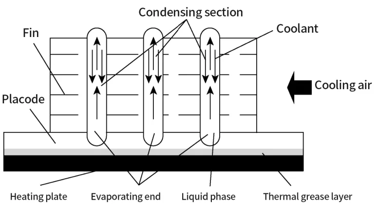
Figure 2: Schematic Diagram of Heat Pipe Heat Sink
Generally, heat pipes are not used as standalone heat sinks; they are typically embedded within fins to enhance the heat dissipation effect.
An analysis of the structure of existing IGBT power device heat sinks shows that by designing and optimizing the array cold-end plane heat pipes, the heat dissipation of the IGBT power devices is improved, thereby enhancing the overall heat dissipation performance.
Figure 3 shows a comparison between the traditional heat pipe heat sink and the array cold-end plane heat pipe.
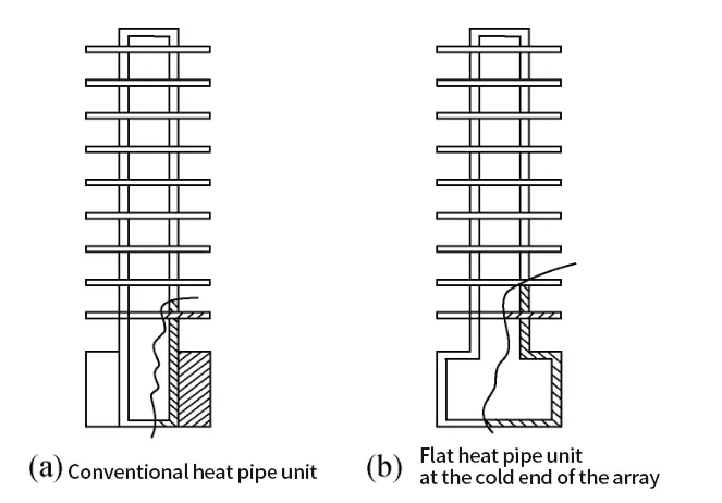
Figure 3: Comparison of Two Heat Pipe Units
Figures 3(a) and 3(b) show the single heat pipe in a traditional heat pipe heat sink and an array cold-end plane heat pipe, respectively. In Figure 3(b), the hollow substrate and the heat pipe are welded together to form a single cavity, with the evaporator end acting as the bottom surface of the entire substrate.
This design increases the heat contact area at the evaporator end and provides a temperature uniformity effect.
By eliminating the thermal resistance of the substrate and the contact thermal resistance between the heat pipe and the substrate, the heat transfer performance is improved.
proposed a new type of symmetric and highly continuous fin array, as shown in Figure 4, which improves natural convection heat transfer by reducing flow resistance.
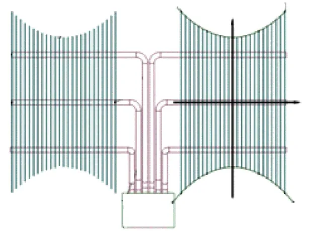
Figure 4: Heat Pipe Heat Sink with Variable Height Fin Array
Through three-dimensional numerical calculations, the heat transfer performance of heat pipe heat sinks with different height-variable fin arrays was compared. The study showed that increasing the spacing between the fins (s) and the maximum height difference of the fins (p) can significantly reduce the material cost per unit power (Mtot), but the effect on the total thermal resistance (Rtot) is more complex. Based on the response surface method, with the goal of minimizing both Rtot and Mtot, a two-stage method combining NSGA-II and TOPSIS was used for parameter research and multi-objective optimization analysis. The resulting Pareto-optimal solutions are regionally distributed in the parameter state map, indicating that s and p are closely related to system performance, rather than being independent.
There are many factors that influence heat pipe heat sinks. By analyzing the heat pipe heat sink, a model was established and numerical simulations were carried out to explore the factors that affect the thermal performance of the heat pipe heat sink:
The thickness and spacing of the fins were studied, and the results showed how the friction factor and heat transfer coefficient change with variations in fin thickness and spacing.
The factors influencing the heat transfer limits of the heat pipe heat sink were also studied, including the condenser section length and the pulsed heat pipe heating section.
The results showed that to maximize the heat transfer capacity, in low fill ratio conditions, the heating section length must be equal to the condenser section length; in high fill ratio conditions, the heating section length must be greater than the condenser section length.
Over the past decade, many researchers have extensively studied many small prototype models, showing that heat transfer performance comparable to diamond substrates can be achieved.
Vapor Chamber (VC)
A vapor chamber is a sealed container similar to a heat pipe that uses phase change to enhance the cooling effect, which has attracted interest in the electronics industry. Some researchers have integrated vapor chambers (VC) between DBC and heat sinks to replace metal substrates and enhance heat dissipation. Zhang et al. studied integrated power electronics modules, replacing the metal substrate with a vapor chamber (VC) integrated between the DBC and the heat sink, eliminating the contact thermal resistance between the module and the heat sink. The model is shown in Figure 6.
Compared to traditional metal heat sinks, the VC spreads the concentrated heat source over a much larger condensation area, offering lighter weight, better geometric flexibility, and a larger cooling area, which significantly enhances the cooling performance of the IGBT module.
A new heat management system for cooling IGBT power modules was developed. The module was integrated with a vapor chamber-based heat sink to reduce thermal resistance and significantly improve temperature uniformity. The model is shown in Figure 6. Compared to traditional heat sinks, the chip junction temperature, internal chip temperature difference, and maximum thermal stress were all reduced, improving the working performance of the IGBT module.
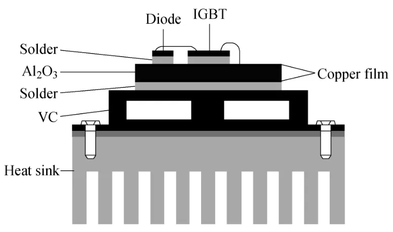
Figure 5: VC-Based Module Structure
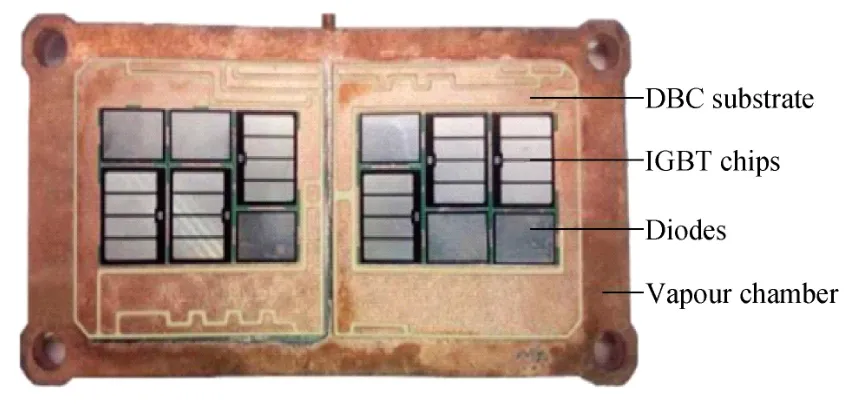
Figure 6: Module Schematic Diagram
Cylindrical heat pipes combined with fins are generally suitable for electronic devices with abundant heat dissipation space. The main advantage of flat heat pipes/vapor chambers is their high temperature uniformity, and they are widely used for localized cooling. In some small power electronics devices, due to the limited heat sources and cooling areas, it is often difficult to effectively use traditional cylindrical heat pipes to enhance heat dissipation.