Cold Plate Design Guide (Part 3): Reliability Considerations for Long-Term Performance
Introduction
After completing the preliminary performance calculations for the cold plate (such as thermal resistance, flow distribution, etc.), the design work is far from over. To ensure the cold plate operates stably, efficiently, and reliably in the actual system, three key technical issues must be addressed:
Flow Resistance Optimization: Ensure the coolant flows through the cold plate with sufficient flow rate to meet heat dissipation requirements, avoiding insufficient system flow.
Pressure Resistance Design: Prevent deformation of the cold plate under operating pressure, which could lead to severe issues such as seal failure (leakage) or poor contact with the heat-generating chip (increased thermal resistance).
Long-Term Operational Reliability: Ensure the cold plate maintains stable performance without degradation during its service life. The core focus is to prevent fin clogging, corrosion, and scaling.
This section will focus on these three aspects, providing design optimization ideas and practical recommendations.
1. Cold Plate Flow Resistance Optimization
Goal: Reduce flow resistance to ensure the system flow meets the heat dissipation requirements.
Challenge: As GPU/ASIC chip power exceeds 1000W and power density increases (~150W/cm²), thinner fins (gap ≤ 0.15mm) are required, leading to a significant increase in flow resistance.
1.1 Conventional Solutions and Limitations:
Traditional Design: Coolant enters on one side of the fins and exits on the other side.
Applicable Conditions: When the fin gap is ≥ 0.2mm, flow resistance is relatively low (typically < 10kPa), which is acceptable.
Problem: When the fin gap is ≤ 0.15mm, the flow resistance becomes too high for this solution.
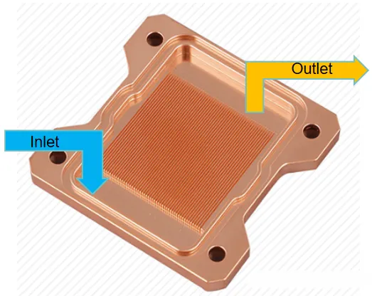
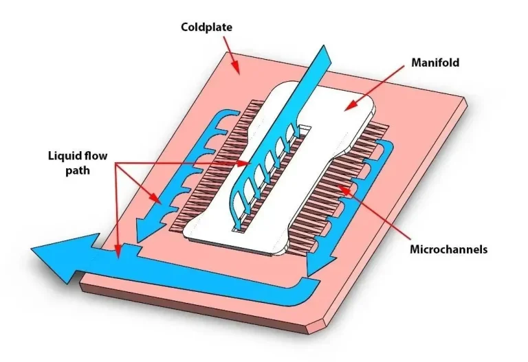
1.2 Optimization Plan: Top-Inlet, Two-Side-Outlet
Principle: The flow between cold plate fins is typically laminar, and the flow resistance △P is approximately proportional to the flow velocity V and fin length L:
△P ∝ K * V * L
Plan Details:
The inlet is moved directly above the fin area.
The outlet is placed on both sides of the fin area.
Optimization Effect:
The flow path length L is halved (equivalent to changing from a single-side to a central flow direction).
With the same total flow rate, the flow velocity V through the fins is reduced by half.
Therefore, the flow resistance △P in the fin area is reduced to about 1/4 of the single-side inlet and outlet configuration.
Advantages:
Significantly reduces flow resistance for cold plates with high power density and small fin gaps, ensuring system flow.
Below is a schematic of this flow configuration, which is used in Coolit cold plates.
II. Cold Plate Pressure Resistance Enhancement
Goal: To prevent deformation of the cold plate under pressure when the substrate is extremely thin (1-2mm), ensuring reliable sealing and good contact with the chip.
Conventional Structure Issues:
Typical Copper Scalloped Cold Plate: There is no welding between the fin tops and the cover plate.
Mechanical Model:
The structure can be treated as a rectangular plate of size length (a) × width (b), with its edges constrained and subjected to uniform pressure (P).
Pressure Resistance Theory (Classic Plate-Shell Theory):
Maximum Allowable Pressure Formula:
P = β * σ * (t / b)²
P: Pressure (MPa)
σ: Material allowable stress (MPa)
t: Cover plate thickness (mm)
b: Plate width perpendicular to the reinforcement direction (mm) – Key dimension
β: Shape factor (depends on aspect ratio a:b)
Required Cover Plate Thickness Formula:
t = b * √(β * P / σ)
Shape Factor β (Influence of Aspect Ratio a:b):
| a:b | β Value |
|---|---|
| 1:1 | 0.307 |
| 2:1 | 0.497 |
| 3:1 | 0.616 |
| 4:1 | 0.697 |
| 6:1 | 0.750 |
Key Conclusion:
When the cold plate fin area dimensions (a × b) are fixed, reducing the width (b) can significantly increase the maximum allowable pressure (P).
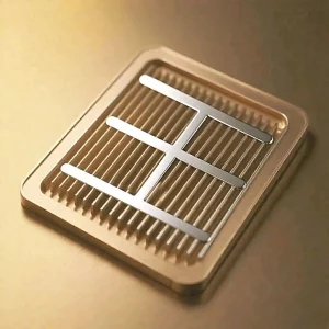
Engineering Solution to Enhance Pressure Resistance:
Add Intermediate Reinforcement Ribs:
Add a support structure in the middle of the fin area.
Weld the cold plate substrate, reinforcement ribs, and cover plate into a rigid integrated structure. (Maintain a 0.05-0.1mm gap between the fins and the cover plate.)
Effect:
This effectively reduces the key dimension b (which becomes the spacing between the reinforcement ribs), significantly improving pressure resistance.

Top Fin Welding:
Weld the tops of the fins to the cover plate, forming a single integrated structure.
Effect:
By using the dense microchannel fins themselves as support points, the structural stiffness and resistance to deformation are greatly enhanced.
When the process is well-executed, it can replace or reduce the use of reinforcement ribs.
This significantly improves the pressure resistance.
Structural Schematic Diagram Below:
Long-Term Operational Reliability of Cold Plates
Goal: Prevent performance degradation (increased thermal resistance, reduced flow, leakage) and ensure stable operation over the long term.
Main Risk Sources:
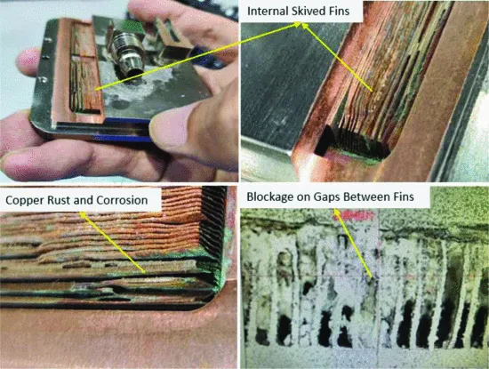
Blockage:
Metal debris, assembly foreign objects, corrosion products, and scale/biofilm deposits accumulate in the narrow gaps between microfins, obstructing fluid flow and heat transfer.Corrosion:
Uniform Corrosion: Copper undergoes slow, uniform thinning in pure water.
Localized Corrosion: More severe damage, including:
Erosion corrosion (significantly accelerated when flow velocity exceeds 1.5 m/s)
Microbial corrosion
Acid corrosion
Pitting corrosion
Stress corrosion
Consequences: Causes fin thinning, strength reduction, sealing failure (leakage), and performance degradation.
Scaling:
Inorganic scales such as calcium carbonate (CaCO₃), magnesium carbonate (MgCO₃), and biological slime deposit on fin surfaces.
Consequences: Significantly increase thermal resistance, reducing heat dissipation performance.
Countermeasures
Filtration:
System equipped with filtration accuracy ≤ 50 μm (300 mesh) to ensure removal of large particles (metal debris, welding slag, etc.).
All components are cleaned before shipment to ensure no large particle residues remain. All pipeline interfaces are sealed with protective caps before delivery.
Water Quality Control (Referencing ASHRAE Standards):
[Follow with specific water quality control measures as needed]
| Parameter | FWS (Primary Water) | TCS (Secondary Water/Coolant) | Objective/Risk |
|---|---|---|---|
| pH | 7 – 9 | 8.0 – 9.5 | Corrosion prevention (copper, stainless steel) |
| Corrosion Inhibitor | Required | Required | Protect metal surfaces |
| Bactericide | – | Required | Inhibit microbial growth (prevent clogging, corrosion, biofilm) |
| Sulfide (H₂S/S²⁻) | <10ppm | <1ppm | Prevent copper sulfide black spots |
| Sulfate (SO₄²⁻) | <100ppm | <10ppm | Prevent sulfate – reducing bacteria proliferation, gypsum scale |
| Chloride (Cl⁻) | <50ppm | <5ppm | Prevent pitting of stainless steel |
| Calcium Hardness (as CaCO₃) | <200ppm | <20ppm | Prevent scaling |
| Bacterial Colony | <1000 CFUs/ml | <100 CFUs/ml | Control microorganisms |
| Total Suspended Solids (TSS) | – | <3ppm | Prevent particulate clogging |
| Conductivity | – | 0.2 – 20 μS/cm | Indicate ion concentration (pure water system) / Control corrosion rate |
| Residue After Evaporation | ≤500ppm | <50ppm | Control total dissolved solids (prevent scaling) |
Note: The requirements for the TCS side (i.e., the coolant circulating inside the cold plate) are much stricter than those for the FWS side.
4. Conclusion
The reliability design of cold plates is a critical factor for the success of high-performance cooling systems and is by no means a simple extension of performance calculations. This article discusses three core dimensions:
Flow Resistance Optimization:
To address the sharp increase in flow resistance caused by narrowed fin spacing under high power density, a “top inlet and dual-side outlet” flow scheme is proposed and validated. This design halves the effective flow path length and reduces flow velocity, significantly lowering the pressure drop in the microchannel region to approximately one-quarter of that in traditional single-side inlet/outlet schemes.Pressure Resistance Enhancement:
Based on classical plate-and-shell theory, the study clarifies the decisive impact of cover plate thickness (t), critical width (b), allowable material stress (σ), and aspect ratio (β) on the cold plate’s maximum pressure resistance (P). Two effective engineering solutions are proposed: adding intermediate stiffening ribs and adopting fin-top welding technology. The former enhances pressure resistance by reducing the critical dimension b, while the latter creates an integrated support structure between fins and the cover plate, representing the preferred approach for improving stiffness and pressure capacity.Long-Term Operational Reliability:
The study systematically identifies three major risks threatening long-term reliability: blockage, corrosion, and scaling. To control these risks, strict water quality management must be implemented on the cold plate’s internal circulating coolant (TCS), with standards significantly exceeding those for the primary water system (FWS). Following ASHRAE guidelines, detailed technical requirements for key water quality parameters—such as pH, corrosion inhibitors, biocides, ion concentration, suspended solids, and microorganisms—are outlined.
Only through meticulous design and stringent control across these three dimensions can cold plates maintain excellent thermal performance, structural integrity, and system stability under high load and long-term operation, providing reliable cooling solutions for high-power electronic devices.