The Design Steps and Common Processing Technologies of Cold Plate Heat Sink
A cold plate is similar to the radiators in air cooling or natural heat dissipation. It is a relatively variable component in liquid cooling design. Most of the other components such as pumps, quick connectors, expansion tanks, degassing tanks, filters and even heat exchangers can be selected from existing mature product series by calculating several key parameters. Therefore, this chapter focuses on the design of cold plate radiators.
- When designing a cold plate radiator, the basic considerations are as follows:
- Strengthen heat transfer by increasing the contact area between the solid and the fluid within a certain volume space;
- Contact the heat source through the thermal interface material;
- There is a contact surface between the fluid and the solid;
- The heat from the heat source is first transferred to the cold plate, and then transferred to the liquid medium flowing in the cold plate, and taken out of the system.
Obviously, the design steps and factors to be considered for the cold plate are similar to those of the radiators in air cooling or natural heat dissipation devices. The only difference is that the fluid medium faced by the cold plate is liquid, while the fluid medium faced by the radiators in forced air cooling or natural heat dissipation is gas. This can also be clearly seen from the following design steps:
Calculating the Flow Rate
Before starting the design of the cold plate, it is necessary to estimate the flow rate required for the system’s heat dissipation. Similar to air cooling, before starting the design of the system’s air duct, it is necessary to estimate the demand for the air volume first.
The formula for calculating the flow rate of the liquid working medium is the same as that for calculating the air volume of a fan. The estimation of the flow rate of the liquid working medium is still based on the law of conservation of energy:
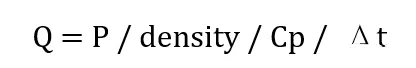
In the formula, Cp is the specific heat capacity of the fluid working medium, and density is the density of the fluid working medium.
Example: The working medium is water, the heat generation amount is 5KW, and the temperature rise between the water inlet and the water outlet is 5℃.
Flow rate requirement:
Q = P / density / Cp / Δt = 5000 / 992 / 4179 / 5 = 2.41 × 10⁻⁴ m³/s = 0.241 L/s
Note: The reference temperature for the physical property parameters of water is 25℃.
Determining the Material of the Cold Plate
In addition to factors such as cost, availability, and processability that need to be considered in any design, the following points should also be paid attention to when selecting the material of the cold plate:
Thermal Conductivity
Common materials for cold plates are copper (alloys) and aluminum (alloys), and both of these metals have relatively high thermal conductivity. In fact, for metal structural
components that serve as the main heat dissipation function in electronic products, the vast majority of materials are copper (alloys) and aluminum (alloys).
Chemical Compatibility with the Liquid Working Medium
Similar to the pump, the cold plate must also ensure its chemical compatibility with the liquid working medium. Usually, electrochemical reactions between the liquid working medium and the cold plate are inevitable. In order to reduce the corrosion rate, a corrosion inhibitor can be added to the working medium. A corrosion inhibitor, also known as a corrosive inhibitor, refers to a chemical substance or complex that, when present in the environment (medium) at an appropriate concentration and form, can prevent or slow down the corrosion of materials. After determining the materials in the system that are in direct contact with the liquid cooling working medium, an appropriate corrosion inhibitor can be selected according to the material properties.
| Cold Plate Material / Liquid Cooling Working Fluid | Water | Ethylene Glycol – Water Solution (EGW) | Deionized Water | Oil | Dielectric Fluid (Fluorinated Liquid) | Synthetic Hydrocarbon (PAO) |
|---|---|---|---|---|---|---|
| Copper Tube | √ | √ | ? | √ | √ | √ |
| Stainless Steel Tube | √ | √ | √ | √ | √ | √ |
| Aluminum Alloy | √ | √ | √ |
Table 11 – 5 Compatibility Table of Common Cold Plate Materials and Working Fluids [7][10]
Note: The cold plate material here refers to the solid material in contact with the liquid – cooling working fluid. A tick (√) in the table indicates compatibility.
Density
In products that require lightweight design, materials with lower density need to be used. In this case, aluminum becomes a very common choice. For example, the cold plates in the power battery packs of new energy vehicles are usually made of aluminum alloy.
Flow Channel Design
In an air – cooling system, generally, the layout of internal heat – generating components is changed, and structural components are added or removed to restrict the direction of air flow, thereby altering the direction and efficiency of heat transfer inside the product. In a liquid – cooling system, the direction of the liquid can be strictly restricted directly through pipelines. Similar to the air in an air – cooling system, as a heat – transfer medium, the direction of the liquid in a liquid – cooling system also directly affects the direction and efficiency of heat transfer.
When designing the flow channels of a cold plate, the following factors need to be considered:
- Heat Source Distribution: The fluid should be as close to the heat source as possible to reduce the spreading thermal resistance.
- Structural Avoidance: This falls within the scope of structural design. The flow channels need to maintain a safe distance from the fixing holes on the cold plate.
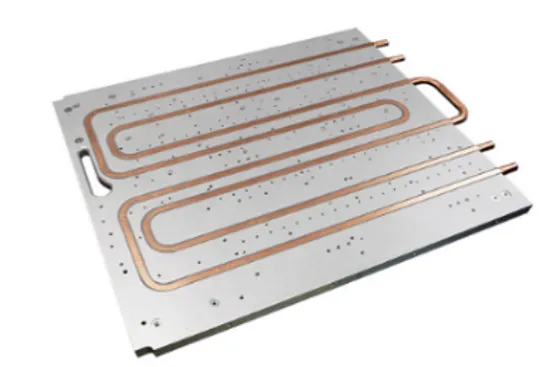
Figure 11-17 The flow channel should avoid the densely arranged fixing holes on the cold plate.
3. Uniform Layout: The fluid should flow over the cold plate as evenly as possible to make effective use of the heat dissipation area. Generally, the farther away from the flow channel, the smaller the contribution to heat dissipation.
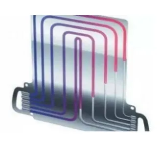
Figure 11-18 The liquid flows evenly across the entire cold plate
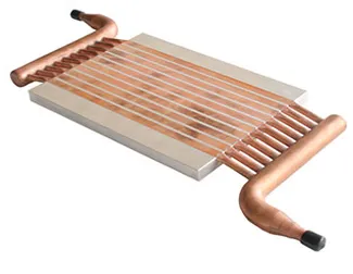
Figure 11-19 Inserted-tube type cold plate with multiple parallel flow channels
- Control of Flow Velocity: The erosion effect of the working medium on the radiator will deteriorate as the flow velocity increases, and the flow resistance will also increase rapidly. However, it is obvious that the higher the flow velocity, the higher the convective heat transfer coefficient. The flow velocity needs to be determined comprehensively by considering the heat dissipation requirements of the product and the available space.
- Minimize Flow Resistance: Design series and parallel flow channels to reduce the flow resistance and the risk of leakage.
- Processability and Cost.
- Design of Pressure Relief and Alarms, etc.: Pressure sensors and temperature sensors should be arranged at reasonable positions in the pipeline to achieve real-time monitoring of the system. When the pressure or temperature is abnormal, necessary control measures should be taken.
Cold Plate Types and Their Advantages and Disadvantages
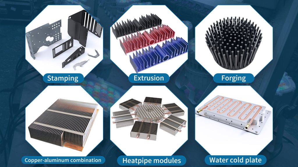
The liquid cooling system has a very wide range of applications, and the characteristics of the product types it deals with vary greatly. Under different requirements, different types of cold plates need to be used. According to the process difficulty, common cold plates can be divided into the following types: drilled type, inserted-tube type, blister type, milled-groove type, extended-surface type, micro-channel type, etc. Their advantages and disadvantages are summarized as follows:
Table 11-6 Advantages and Disadvantages of Common Cold Plates
| Cold Plate Type | Advantages | Disadvantages |
|---|---|---|
| Drilled – type | Simple processing technology; Heat – generating components can be placed on both sides of the cold plate. | The internal flow channel is realized by mechanical drilling, resulting in low production efficiency; Only relatively simple flow channel designs can be used, and the right – angled intersection of the flow channels leads to a relatively large flow resistance; The cross – section of the flow channel can only be circular. |
| Inserted – tube type | Simple processing technology, high production efficiency, and relatively low cost; The shape of the flow channel can be realized by bending the tube; The material of the inserted tube can be different from that of the cold plate substrate to avoid corrosion. | There may be contact thermal resistance between the inserted cold tube and the substrate; The shape of the flow channel is affected by the bending radius of the pipeline – the smaller the bending radius, the greater the flow resistance. |
| Blister – type | High production efficiency and low cost; The flow channel design is relatively flexible, realizing a large – area contact between the fluid and the metal wall surface, with high heat exchange efficiency; Blind holes are opened on one side, and the blind holes can be located at any position without interfering with the flow channel. | The substrate is relatively thick, making the cold plate bulky; Components need to be located on the thick side, resulting in a relatively large thermal resistance. |
| Milled – groove type | The flow channel design is very flexible, and flow channels with good matching of flow resistance and heat exchange can be designed according to requirements; Heat sources can be placed on both sides; Milled – groove cold plates with vacuum brazing or friction stir welding have good sealing performance. | Welded – type milled – groove cold plates have high process difficulty and low production efficiency; Non – welded milled – groove cold plates have difficulty in ensuring sealing performance. |
| Extended – surface type | High heat exchange efficiency; High production efficiency. | Relatively large flow resistance; High requirements for the liquid – cooling working fluid, otherwise it is easy to be blocked. |
| Micro – channel type | The highest heat exchange efficiency can be achieved; The fluid flows over the entire surface of the cold plate, with good temperature uniformity; The cold plate is light and thin. | Relatively large flow resistance; High requirements for the liquid – cooling working fluid, otherwise it is easy to be blocked. |
Liquid cooling design has many characteristics that are different from air cooling. This chapter describes the differences among different liquid cooling design schemes, and introduces the design steps of liquid cooling schemes as well as the matters that should be noted in each link. The cold plate is a key material in liquid cooling design. To some extent, it determines the forms of the liquid cooling working medium, pump, heat exchanger, etc., and there are numerous variations. With the increase of the power density of products, the application of liquid cooling will become more and more widespread. In fact, the design difficulty and the factors to be considered are extremely complex. For the system-level liquid cooling design in industrial equipment, it is even necessary to take into account the characteristics of the building itself.