The selection of LED heat dissipation and cooling technology

LED Lighting


There are two main areas in LED lighting that make LEDs attractive as alternatives to standard lighting: (1) energy savings and (2) easier control and management of light response. Energy saving is certainly appealing and has become the strongest driving force behind the attractiveness of LEDs.

As shown in Figure 1, within the visible light spectrum, the efficiency of an LED is approximately three times that of a comparable incandescent lamp.

Figure 1: Electricity Consumption of LED and Incandescent Bulbs

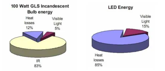
LEDs still generate heat and require cooling, but the light output at the same power is more efficient than the standard lighting technologies that have been used for many years.

The role of heat and LED response

The combination of generated heat and control of response time brings cooling issues to the forefront of LED lighting. As mentioned above, the easily controllable light output makes LEDs attractive for many applications, ranging from cosmetics to industrial, home, and street lighting.

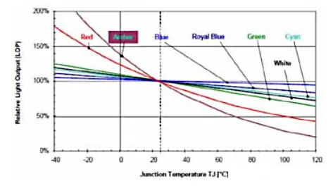
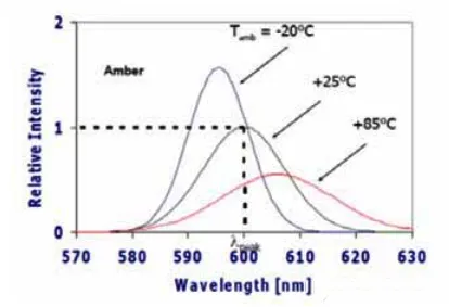
Because LEDs are semiconductor devices, their light output is directly affected by temperature. Figure 2 clearly shows how the relative light output (LOP) is influenced by temperature.

Figure 2: The Impact of LED Junction Temperature on LED Light Output

Lorem ipsum dolor sit amet, consectetur adipiscing elit. Ut elit tellus, luctus nec ullamcorper mattis, pulvinar dapibus leo.

For amber and red lights, significant swings in relative light output are noticeable across the entire temperature range of typical designs.


The color least affected is blue, with its variation being only a few percentage points compared to other colors. Such fluctuations in light output are clearly measurable, even within the lower temperature ranges that are most common in various deployment sites.


Obviously, similar to any other semiconductor devices, the expected lifespan of LED devices is highly dependent on temperature. Figure 3 clearly demonstrates the crucial role of temperature in maintaining a longer lifespan for LEDs.
Figure 3: Service life of high-brightness white LEDs at different operating temperatures
Figure 3 clearly shows that if the junction temperature of the device is reduced by 11°C, the expected lifespan increases by 35,000 hours. Additionally, by increasing the LED temperature, several key characteristics may become more pronounced.


A rise in temperature directly affects the forward voltage of the LED, causing it to decrease, which increases the load on other components driving the LED and leads to their temperature rise. The increase in temperature causes a change in wavelength, as shown in Figure 4.


Wavelength changes can cause orange LED lights to appear red or white LEDs to exhibit a blue hue. Similar to any other semiconductor device, if the thermal situation is not managed, it will result in catastrophic failure of the LED.


Therefore, for controlling the lifespan and color display of LEDs, thermal management becomes central to the successful deployment of LEDs, regardless of the installation location.
Figure 4: The Effect of Temperature on the Emission Wavelength of LEDs

Understanding LED Heat Transfer

Although the functionality of LEDs has not changed, the packaging of LEDs has undergone significant changes over the past few decades.


The changes in packaging have significantly improved the thermal performance of LEDs. As shown in Figure 5, it is clear that the evolution of semiconductor packaging has reduced thermal resistance by an order of magnitude.
Figure 5: Trends in LED Packaging and Reduction in Thermal Resistance

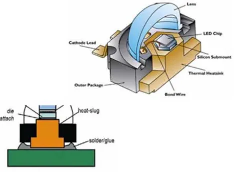
As the top surface is covered by a lens that must expose the emitted light, typical LEDs today are designed to transfer heat from the device’s back to the printed wiring board (PWB) as efficiently as possible, as illustrated in Figure 6. This is usually achieved with a thermal slug, which serves as the interface to the PWB.

Figure 6: LED Packaging - Using a heat sink to transfer heat from the semiconductor device to the printed wiring board (PWB)

To minimize contact resistance between the thermal slug and PWB, the following measures can be employed: interface materials, soldering (when electrical isolation is required), or more recently, constructing the entire LED structure directly on the PWB.

Several approaches exist for transferring heat from the LED to the non-component side of the PWB: using filled vias, embedded thermal slugs within the PWB, copper layers, graphite foam, etc.

Once heat enters the PWB, it transfers to the backside (non-LED side) and is dissipated into the ambient environment via natural convection or active high/higher-capacity cooling systems.
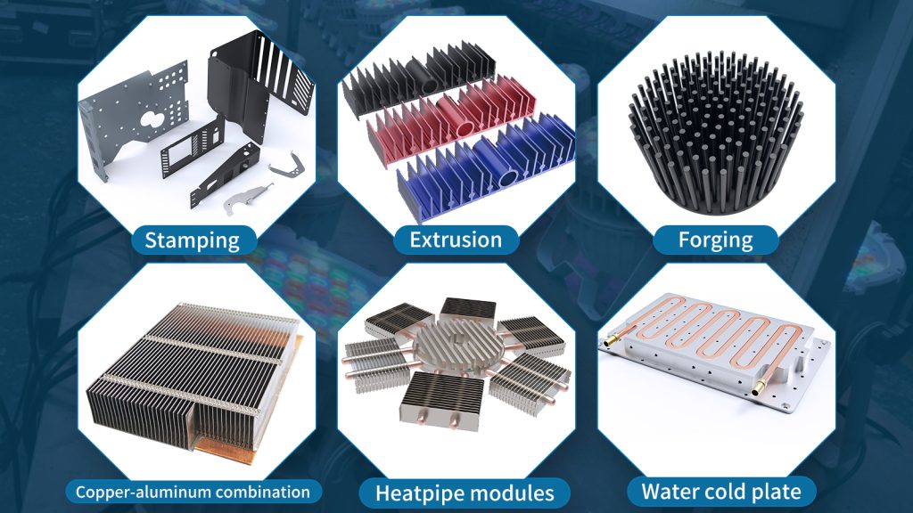

Cooling Options

Similar to other semiconductor devices, cooling solutions for LEDs span a broad spectrum: ranging from simple copper plates or heat sinks for thermal diffusion to complex cooling systems potentially incorporating liquids or refrigerants.

System Classification:


  • Passive Systems: Contain no moving components (e.g., heat sinks alone)

  • Active Systems: Incorporate maintainable parts such as fan-cooled heat sinks or TECs (Thermoelectric Coolers—commonly known as Peltier devices or semiconductor refrigerators)

Active systems require external power to drive cooling components (fans, pumps, TECs, etc.). Selection criteria for cooling solutions include:

  1. Cooling Efficacy: Can it achieve the required junction temperature uniformity across LED arrays?

  2. Cost-Effectiveness: Does the combined cost of LEDs and the cooling system ensure economic viability?

  3. Site Adaptability: Does it meet acoustic requirements of the deployment environment?

  4. Power Consumption: Will cooling energy expenditure compromise LED’s cost advantage over traditional lighting?

  5. System Reliability: What are the maintenance demands and failure rates?

  6. Environmental Impact: What is the carbon footprint across its lifecycle?

Design Principle:


Simpler systems are preferable when meeting thermal and temperature uniformity targets (e.g., opting for copper/aluminum plates if weight permits). However, high-brightness LEDs necessitate enhanced cooling for increased thermal loads.

Critical Consideration:


Criterion #3 (Site Adaptability) is paramount. For example:

Consider an LED streetlight with an active cooling system. A fan failure due to prolonged high-temperature operation would require:

  • Replacing the fan

  • Implementing smart alerts to a control center

  • Deactivating the LED until repairs are completed
    Such maintenance costs may undermine economic feasibility. Here, designers should prioritize passive cooling solutions.

Technological Advances:


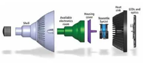
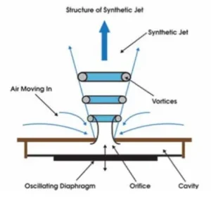
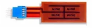
Various active cooling technologies—successfully deployed in electronics—include synthetic jet actuators that drive airflow within LED housings. Figure 7 demonstrates an implementation using Nuentix Synjet™ for LED cooling.

Figure 7: Cooling of High-Power LEDs Using Synthetic Nozzles

Although it does not have blades like a traditional fan, it can generate air movement by producing oscillations through a diaphragm, as shown in Figure 8.

Figure 8: A cross-sectional view of a synthetic jet, showing an oscillating diaphragm used to generate air movement

Cooling Options in Broad Terms

  • Piezoelectric fans: Recommended for more localized cooling in low-power applications, as these devices generate localized flows and enhance the heat transfer coefficient of LEDs cooled by natural convection.
Figure 9: Piezoelectric Fan for LED Cooling

Cooling Options

  • Fan-cooled heat sinks: These devices require fixing a fan on the top of a heat sink, which is then connected to the back of the PCB in the LED enclosure.
  • Jet impingement devices: In this configuration, air is directed onto the hotspots on the back of the LED array to provide more effective cooling than fan-cooled sinks.
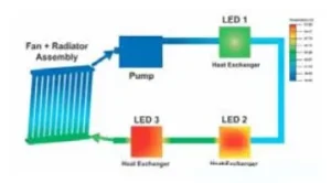
  • Liquid cooling: A cold plate is attached to the PCB carrying the LEDs, which is then connected to a liquid loop containing a reservoir with a liquid-to-air heat exchanger and a pump. Typical applications of such systems are very high-power lighting scenarios where a well-designed cooling system justifies the deployment.
Figure 10: Schematic diagram of a liquid cooling system for an LED display application

Freezing Cooling

In this solution, a refrigeration cycle is used to cool the LEDs, with the evaporator of the refrigeration cycle placed on the back of the PCB housing the LEDs. Similar to liquid cooling, the application of such complex systems depends on the scenario and whether using LEDs justifies the design compared to other lighting sources.

Key Design Considerations for LED Thermal Management

All designers involved in LED lighting must prioritize two critical factors at the forefront of their design process: contact resistance and diffusion thermal resistance.

Contact Resistance

From a cooling perspective, the contact resistance when LEDs interface with the PWB (or when the LED-PCB contacts the cooling system)—regardless of whether the system is active or passive—must be minimized. Using gap fillers, improved manufacturing processes (e.g., flatness control), and integrated structures that merge LEDs with cooling systems will be pivotal for thermally challenging lighting systems.


An excellent designer will further ensure that all contact resistances along the heat transfer path from the semiconductor to the final environment are minimized, ensuring unobstructed heat flow and minimal temperature gradients beneath the LEDs.

Diffusion Resistance

Since we deal with discrete heat sources attached to larger heat sinks or cold plates, diffusion resistance plays a vital role in effective thermal management. Typically, depending on design and material choices, diffusion resistance is the primary parameter hindering heat dissipation. Regrettably, its minimization is often overlooked by many designers, leading to unnecessarily complex cooling systems.


Understanding the heat flow from the heat source to the heat sink (e.g., the ambient environment) and minimizing diffusion resistance can mean the difference between a simple heat sink and a complex cooling system.

Conclusion

An LED—more accurately, solid-state lighting—shares the same fundamental principle as any other electronic device: its lifespan and proper operation depend directly on its junction temperature and thermal management.


Cooling technologies for LED thermal management are readily available and deployed across various electronics markets. No new heat transfer phenomena remain unaddressed. The challenge for designers or manufacturers lies in aligning the cooling system/solution with the deployment site’s requirements and market acceptability.


Imagine entering your home office or room illuminated by LEDs, only to be greeted by the noise of fans or synthetic jets. The hum of a PC or HVAC is already uncomfortable—now consider the impact of 12 LEDs.


Thus, the challenge for LED lighting designers is not the cooling technology itself (which is off-the-shelf) but packaging that technology such that LED lamps or systems become a more viable choice compared to other lighting options.

Latest Blog

From Concept to Mass Production – Your Professional Heat Dissipation Solution Partner

Scroll to Top

contact Ecotherm

We are available to assist you via email. Please don’t hesitate to get in touch, and we will respond to your inquiry as soon as possible.


Email:  support@ecothermgroup.com

Follow us on YouTube | TikTok | LinkedIn
Stay connected with us for updates, news, and more!


Please fill out the form below, and we will get back to you as soon as possible.

Contact Ecotherm

Please upload your design or requirements, and our experts will provide a precise cooling solution tailored to your needs.