Thermal Resistance Network System of IGBT Power Devices
In general, the downward heat dissipation path of IGBT power devices can be described as follows: when the IGBT power device is powered, it generates a large amount of heat due to conduction losses and switching losses on the IGBT chip under the influence of voltage and current.
The heat dissipation path from top to bottom is: chip → ceramic copper-clad substrate → baseplate → heat sink.
The heat is ultimately carried away from the heat sink to the air through convective and radiative heat transfer, using either active or passive cooling methods.
Throughout the conduction process, there is thermal resistance, which is a key factor influencing the heat dissipation of IGBT power modules.
To enhance the cooling effect, reducing thermal resistance is the primary method.
Figure 1 shows the thermal transfer schematic of an IGBT power module in an inverter welder. The chip, ceramic copper-clad substrate, and baseplate are soldered together using a soldering process.
Thermal conductive silicone grease is applied between the baseplate and heat sink to enhance thermal conductivity.
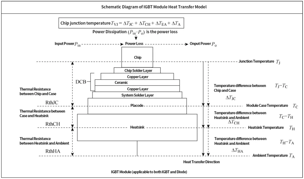
Figure 1: Thermal Transfer Schematic of IGBT
In the system structure of the IGBT power module in an inverter welder, the heat flow transmission path can be analyzed as follows: chip → chip solder layer → copper → ceramic → copper → system solder layer → placode → thermal conductive silicone grease → heat sink → environment. Yin Jiong et al.
proposed a method using a thermal resistance equivalent circuit to determine the impact of heat resistance parameters of the cooling system on the total system resistance.
The parameters include the material and structural characteristics of power components, the contact condition between the heat sink and the module surface, etc.
The results showed the effect of different airflow speeds on the cooling performance and the minimum airflow speed required to ensure the reliable operation of the module.
Deng Erping et al. conducted thermal resistance testing using two different methods and compared the results.
The study found that the traditional thermocouple method is only suitable for measuring the thermal resistance from the junction to the shell in soldered IGBT modules.
The transient dual-interface method is suitable for measuring the thermal resistance from the junction to the shell in both soldered and press-fit IGBT modules.
The thermal resistance network primarily consists of three components: material volume thermal resistance, thermal interface material thermal resistance, and component-to-environment thermal resistance.
Therefore, the total thermal resistance model from the IGBT chip to the environment can be expressed as:
Where:
Rjc is the thermal resistance from the IGBT chip to the copper baseplate,
Rcs is the thermal resistance from the copper baseplate to the heat sink,
Rsa is the thermal resistance from the heat sink to the external environment.
Currently, the internal structure of IGBT power modules is quite mature. It is well-known that reducing the interface thermal resistance and material thermal resistance inside the module is very difficult. Therefore, current research focuses on the study of RsaR_{sa}Rsa, with the goal of reducing thermal resistance and quickly dissipating the heat generated by the module into the air to lower the module temperature. This paper primarily reviews the heat dissipation technologies for IGBT modules to the environment, which are mainly divided into active and passive cooling. The cooling technologies include heat pipe cooling, PCM-based heat sinks, air jets, and liquid jets.
IGBT Power Module Heat Dissipation Analysis and Design
As a core component for energy conversion and transmission, IGBT is widely used in industries such as chemicals, metallurgy, rail transportation, and new energy.
It has made significant contributions to mitigating the global fossil energy crisis and environmental issues by promoting the use of sustainable clean energy.
Power modules dissipate heat into the atmosphere through heat conduction, convection, and radiation.
Due to different heat densities and application scenarios of IGBT, different cooling methods are required, mainly divided into passive cooling and active cooling.
The primary difference between them is that passive cooling dissipates heat into the atmosphere through natural convection without the assistance of external forces, while active cooling utilizes forced convection heat transfer through air cooling or water cooling, using external forces to dissipate heat into the air. Passive cooling has a simpler structure, lower cost, and higher reliability, but the heat dissipation effect is less noticeable.
Active cooling, on the other hand, provides better heat dissipation and faster cooling due to the assistance of external forces.
By applying a thermal resistance network system model, the heat dissipation analysis and design of IGBT power modules can potentially achieve optimal cooling performance.