Tube Cold Plate Design: Matching Tubes to Heat Sources
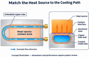
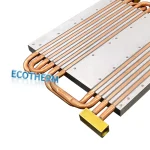
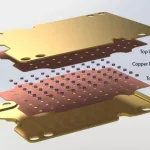
A tube cold plate carries coolant through tubing embedded in a metal base. The base provides the mounting surface and conducts heat toward the tube. For a buried-tube design, the heat path includes the base, the tube-to-plate contact, the tube wall, and the coolant inside it. The tube and base therefore have different jobs, even when both are made from highly conductive metals.
For a custom plate, the practical question is where to put that tube. A neat serpentine pattern does not establish whether every power module will stay within its temperature limit. Start with the actual heat-source layout, then develop a route that also fits the mounting holes, ports, available space, and cooling conditions.
The tube-embedded cold plate construction provides the product background. This guide focuses on matching the tube route to the equipment it must cool.
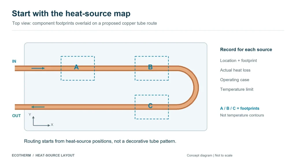
Start with a heat-source map
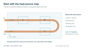
Mark each component that transfers heat into the plate. Show its position, contact footprint, mounting pattern, and orientation on a drawing with a common datum. A component’s outline and its effective contact area may differ, so identify both where necessary.
For each operating case, record the heat the plate must remove. A converter’s output rating is not its heat loss. Use calculated or measured losses for the relevant operating conditions, and identify estimates that still need confirmation.
| Information | What to mark or record | Why it affects the tube route |
|---|---|---|
| Heat-source position | Coordinates and contact footprint | Shows where heat enters the base |
| Heat loss | Loss for each source in each operating case | Identifies concentrated loads and simultaneous operation |
| Temperature limit | Allowed value and measurement location | Establishes which interface or component must meet the limit |
| Mounting interface | Hole pattern, contact surface, and specified TIM | Defines the thermal and mechanical interface |
Keep temperature references clear. A junction-temperature limit, a module case-temperature limit, and a cold-plate surface limit describe different locations. The thermal review must account for the path between the specified limit and the coolant.
Eaton’s custom cold plate design guidance likewise starts with component dimensions, locations, heat loads, and temperature limits, together with the coolant and hydraulic constraints.
Keep the map linked to the current drawing revision. Moving a module or changing its operating losses can require a different route, even if the outer plate dimensions stay the same.
Match the tube route to thermal and mechanical constraints
Review how heat from each footprint reaches the tube. A route passing near a module may still require heat to spread laterally through the base. The distance, remaining base thickness, and tube-to-plate contact all need consideration. There is no universal tube spacing that establishes adequate cooling for every assembly.
Radian’s cold plate performance white paper illustrates embedded tubing and its attachment to the base. That interface is part of the heat path, rather than a detail to leave until after routing.
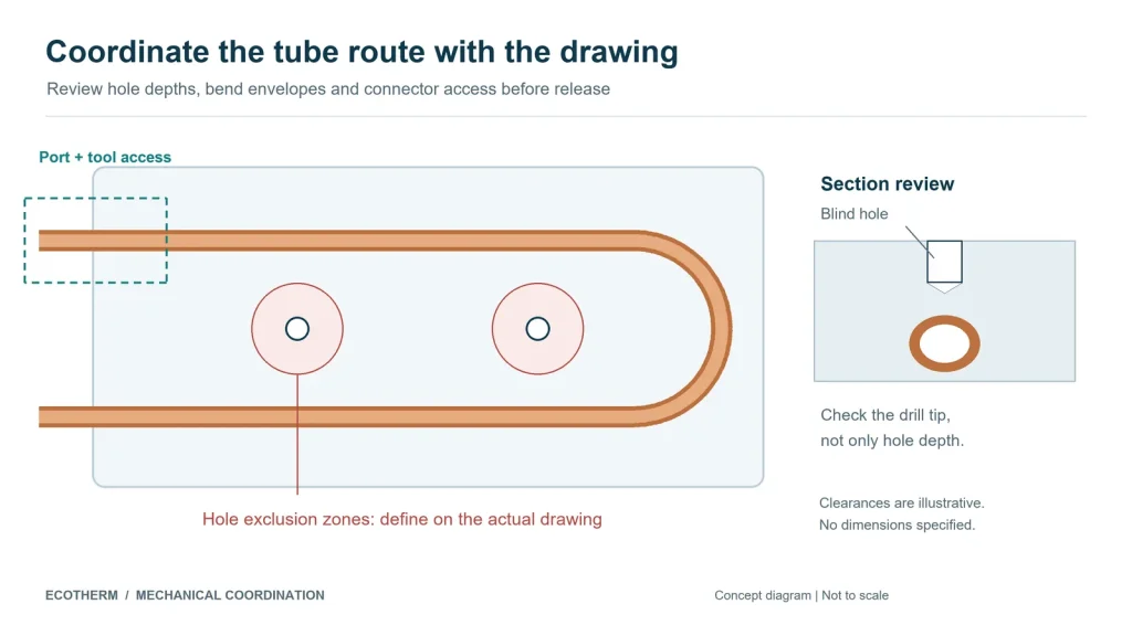
Next, overlay the mechanical drawing. Check:
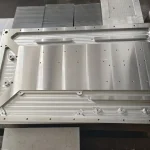
- Mounting holes, including blind-hole depth and drill-tip geometry.
- Tube outside diameter, groove geometry, and the space needed for bends.
- Inlet and outlet positions, hose routing, and connector access.
- Assembly clearance and access for installation tools.
Review these features in section as well as in plan view. A hole that appears clear of a tube centerline can still intersect the tube or its groove. Specify exclusion zones and permitted machining depths for the actual design. ATS’s published cold plate drawings show why machining restrictions belong on the drawing; their dimensions apply to those products, not to every cold plate.
Tube forming also matters. A distorted bend changes the flow cross-section, while unnecessary intermediate joints introduce additional potential leak locations. Eaton discusses these issues, along with tube-to-plate contact, in its tubed cold plate quality guide.
Use bend limits confirmed for the selected tube and forming process. Continuous tubing can reduce intermediate joints, but it does not remove the need to verify the finished assembly.
Compare routes at the flow the plate will receive
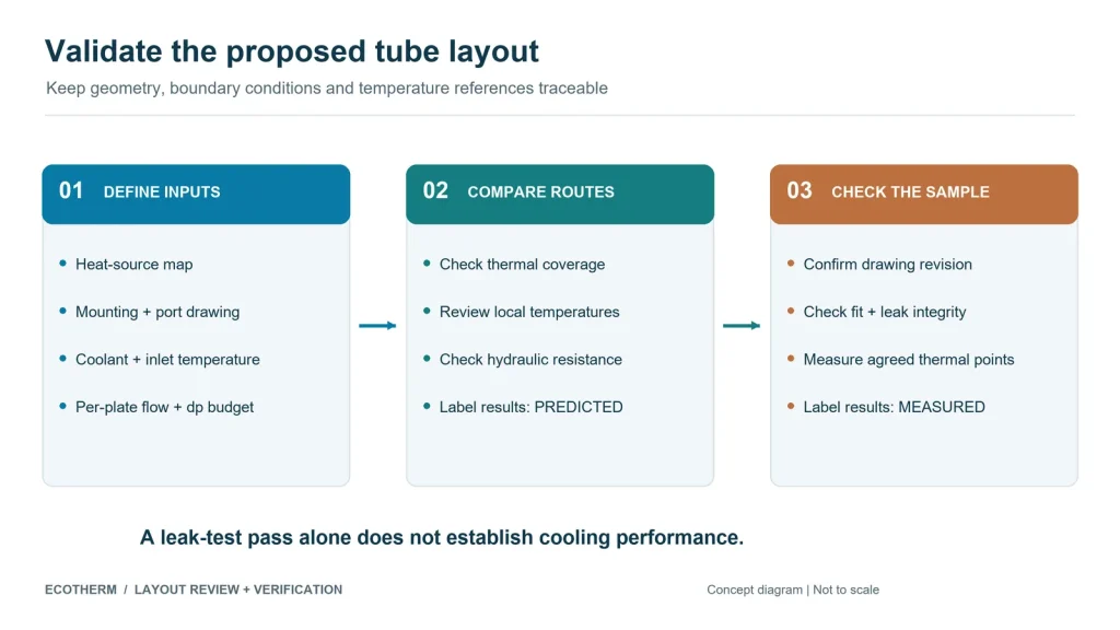
Once the geometry is feasible, compare candidate routes under the same operating conditions.
Keep the heat-source map, contact assumptions, coolant composition, inlet temperature, and temperature references consistent.
Use the flow available through the individual plate. A pump’s headline rating does not establish that flow once the plate, hoses, fittings, and other circuit components are installed.
Adding passes can bring tubing closer to more heat sources, but it also adds flow-path length and bends. Check the resulting thermal behavior together with hydraulic resistance. Our guide to cold plate pressure-drop and flow curves explains how to compare data at a defined operating point.
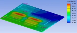
Review the temperature at every critical source. An acceptable average plate temperature or coolant outlet temperature does not establish that a locally concentrated load meets its limit.
Consider source order along the flow path as well: coolant warms as it absorbs heat, while each device may have a different temperature allowance.
Keep CFD predictions separate from measurements. Simulation can help compare routes; a prototype can then check the proposed assembly under agreed conditions. Record the drawing revision, heat-source arrangement, mounting interface, coolant, flow, and measurement locations with the results.
Recognize when a tube layout needs a different approach
A feasible tube route may still miss the temperature target. Before adding more tubing, identify the limitation: heat spreading through the base, tube-to-base contact, local heat transfer into the liquid, or insufficient installed flow.
Radian’s white paper compares embedded-pipe and immersed micro-fin concepts under specified conditions. Its useful lesson is to compare complete designs against the same requirement; its results are not a universal ranking for every application.
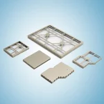
Reconsider the construction when the tube cannot approach critical heat sources without conflicting with mounting features, or when thermal requirements cannot be met within the available flow and pressure-drop budget. Other custom liquid cold plate structures may offer different options for internal geometry and integration.
The decision should follow the thermal and mechanical review. A familiar manufacturing route is useful only when the resulting part meets the equipment’s requirements.
Send the heat-source layout with your drawing
or a useful tube-routing review, send the mounting drawing and a marked heat-source map together. Include the losses and temperature limits for the operating cases the plate must handle, plus the available coolant conditions.
If only some inputs are final, identify what is fixed and what can change. For example, the module mounting pattern may be fixed while port positions remain open for discussion. This helps avoid a proposal that solves the cooling problem but cannot fit the assembly.
Before releasing a prototype, agree on dimensional checks, leak-test conditions and acceptance criteria, and any thermal or hydraulic verification required. A successful leak test alone does not establish cooling performance.
Planning a custom tube cold plate? Send your drawing, heat-source locations, and cooling conditions to support@ecothermgroup.com for a project review.