Cold Plate Flatness for IGBT Modules: What to Specify on Your Drawing
Cold plate flatness should be specified for a defined mounting area, with an agreed inspection condition—not as an isolated number. Start with the exact IGBT module’s installation requirements, then check the contact geometry, thermal interface material (TIM), fastening arrangement and cold plate manufacturing route.
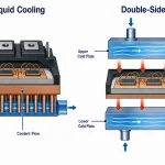
This guide focuses on modules mounted to a separate cold plate through a thermal interface. Not every liquid-cooled module uses that arrangement: Infineon’s HybridPACK 2, for example, incorporates a liquid-cooled pin-fin baseplate and does not require thermal grease at the cooler interface. Its installation instructions should not be substituted for those of a conventional TIM-mounted module. Infineon HybridPACK 2 mounting guidance
The aim is to give engineering, purchasing and the supplier the same definition of an acceptable mounting surface.

Flatness vs. Surface Roughness: Control the Right Feature
A cold plate can have a smooth, reflective surface and still be bowed across a module mounting area. It can also meet a flatness requirement while retaining surface texture that needs separate evaluation. One characteristic does not establish the other.
Flatness describes surface form. Its tolerance zone lies between two parallel planes; the form control does not itself require a datum. It does not establish the surface’s location or orientation relative to another feature. KEYENCE’s explanation of form tolerances illustrates this distinction.
| Characteristic | What it controls | What it does not establish |
|---|---|---|
| Flatness | Departure from a planar form over the specified surface | Surface texture or alignment with another surface |
| Surface roughness | Surface texture evaluated using a defined parameter and method | Overall bow or relative mounting-pad height |
For roughness, preserve the parameter named in the applicable requirement. Ra and Rz are different profile parameters; the same numerical value cannot simply be substituted between them. Fuji specifies Rz in its MT6M10210g module mounting instructions.
Read the parameter, units and measurement definition together. A request for a “polished finish” does not provide an acceptance criterion for either surface form or roughness. Identify the characteristic that affects the assembly before selecting its limit.
Define the Module Mounting Areas Before Choosing a Tolerance

Start with an assembly layout. Identify where each module contacts the cold plate, where screws or clamps apply load, and how the plate attaches to the equipment.
The mounting region can extend beyond the thermal contact patch. Fuji’s MT6M10210g instructions include the module mounting area and its two clamps. For that manual’s applicable modules, it specifies an absolute surface deviation limit of 50 µm per 100 mm, using the mounting-hole centers as a reference. This is a product-specific instruction, not a universal cold plate tolerance. Do not automatically turn length-based guidance into an area-wide drawing requirement; have the responsible engineer approve its translation into the drawing.
For a plate carrying several modules, separate three questions:
Does each local mounting surface meet the applicable module requirements?
Could whole-plate bow or twist interfere with the mounting arrangement?
Do modules, busbars, boards or other connected parts impose relative-height or alignment requirements between mounting areas?
Applying flatness separately to several pads does not, by itself, establish their relationship. Additional controls may be necessary, but they should follow the assembly requirements rather than an assumption that every surface must share one plane.
Local machining can sometimes avoid finishing an entire plate to the tightest requirement. Eaton’s cold plate manufacturing guidance discusses that option for multi-module layouts. It also notes that removing material from thin-walled plates can compromise remaining wall thickness and pressure capability. Machining allowance is therefore a design constraint, not an unlimited correction for distortion.
Do not assume mounting bolts will pull an unsuitable plate into an acceptable condition. If the design depends on a prescribed restrained state, define and validate that condition.
Match the Surface Requirement to the Module, TIM and Fasteners
Before requesting tighter machining, check the module’s installation instructions, the TIM and the fastening arrangement together. A cold plate specification cannot compensate for an unsuitable interface material or an assembly procedure that the module manufacturer does not permit.
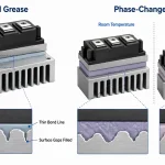
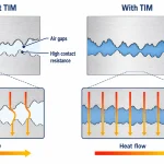
Thermal grease fills gaps between mating surfaces. It should not be treated as a general remedy for excessive distortion. Fuji explains that an overly thick grease layer can impede heat transfer, while insufficient grease can leave gaps. The material, application method and thickness must suit the module and its installation requirements. Fuji IGBT cooling design manual
Also distinguish applied grease thickness from the bond-line thickness after assembly. These describe different stages. If the project specifies an assembled bond line, agree how it will be achieved and verified rather than assuming that the initial application produces the same final thickness.
Fastener torque is equally important. Insufficient tightening can leave poor contact or a loose assembly; excessive tightening can damage the module case. Follow the product-specific torque and tightening procedure instead of increasing torque to pull a distorted plate into contact.
Infineon’s Easy-module instructions likewise address module-dependent grease application and preventing the module from lifting during mounting. They illustrate why a generic grease thickness or tightening sequence is not a substitute for the applicable installation instructions. Infineon Easy-module assembly instructions
When comparing IGBT cooling solutions, consider the complete interface: module construction, contact geometry, TIM and mounting hardware—not cold plate flatness alone.
What to Specify on the Drawing and Technical Agreement
A usable drawing connects each requirement to a defined region, manufacturing state and verification condition. Begin with the module part number and mounting-manual revision, then express the requirements using the project’s agreed drawing conventions.
Use the following checklist for engineering review. The approved drawing and technical agreement—not this checklist—govern product acceptance.
| Drawing item | What to make explicit |
|---|---|
| Mounting regions | Identify each module contact area and relevant clamp or support area. Show the boundaries. |
| Geometric requirements | Define the extent of each control. Separately address required pad-to-pad height, orientation or other assembly relationships. |
| Surface texture | Specify the parameter, units and applicable definition, with the evaluation conditions needed for consistent interpretation. |
| Final surface condition | State whether acceptance applies after joining, finish machining and surface treatment. Identify coating exclusions or masking requirements. |
| Assembly references | Identify the applicable module installation instructions, TIM specification and mounting procedure by revision. |
| Verification condition | Specify the free state or defined restrained state, referencing the agreed inspection procedure. |
| Controlling documents | Identify the drawing revision, requirement references and inspection records. Resolve document conflicts before production. |
For surface texture, the parameter alone may not fully describe the measurement. Filtering, evaluation length and the measurement direction or location can matter. Agree on these details under the applicable specification rather than letting the supplier and customer use different settings. Mitutoyo’s surface roughness guide explains the relationship between profiles, parameters and measurement conditions.
Keep the manufacturing sequence visible. If joining, coating or final machining follows an intermediate inspection, that earlier result should not be presented as proof of the finished surface condition.
These interface details belong alongside the wider cold plate mechanical design requirements, not in place of them. Clear mounting-face requirements do not replace checks on structural loads, fluid connections or the rest of the assembly.
Agree on Inspection Conditions and Acceptance Records
Before approving a sample, agree on how the finished mounting surface will be measured. Define the acceptance stage and whether the relevant surface is coated, masked or uncoated. Label intermediate checks separately.
Support and restraint need equal attention. Clamping can change the shape being measured; excessive restraint may conceal distortion rather than demonstrate compliance. Define support locations and any required clamping arrangement. If both free-state and specified restrained measurements are needed, report them separately. Do not add clamps simply to obtain a passing result.
Allow the part and equipment to reach suitable thermal stability. Plan measurement coverage across the functional regions rather than checking only convenient locations. These are established concerns in the NPL guide to CMM measurement strategies, which discusses workholding, temperature and sampling.
Agree on the evaluation method as well as the measurement locations. Raw maximum-minus-minimum height readings are not automatically equivalent to the specified flatness result: interpretation depends on alignment, the evaluated region and the calculation method.
Choose a measurement approach suited to the part size, surface, access and tolerance. A CMM, a surface-plate-based setup with suitable probing, or a qualified optical method may be appropriate. Suitability must be demonstrated for the actual task; a machine’s headline specification is not the same as task-specific measurement uncertainty. NPL’s guidance on CMM uncertainty addresses this distinction.
Display resolution, repeatability and measurement uncertainty are not interchangeable. More displayed digits do not, by themselves, demonstrate a more accurate result. Agree on the acceptance decision rule, including the treatment of uncertainty where relevant. NIST’s measurement uncertainty guidance provides background.
A useful report can use the following fields:
| Field | What to record |
|---|---|
| Part identification | Part number, drawing revision, batch or serial identification, and inspection zone |
| Acceptance stage | Final manufacturing and surface-finish condition |
| Support and restraint | Support points and specified clamping, if applicable |
| Thermal conditions | Relevant temperatures and stabilization conditions |
| Measurement system | Method, equipment identification and calibration status |
| Coverage and evaluation | Measurement locations, exclusions and calculation method |
| Results | Values and units for each specified region and characteristic |
| Decision | Applicable requirement, acceptance rule and uncertainty where relevant |

What to Send for a Cold Plate Review
For an initial discussion, send your module part number or available drawing, a brief application description, and any known mounting-surface concern. You do not need a complete thermal specification to start the conversation.
For a detailed assessment, add the module layout, installation instructions, TIM and fastening details, available thermal and coolant conditions, and expected prototype and production quantities.
To discuss custom liquid cold plate manufacturing, share your drawings and existing installation requirements with Ecotherm. Identifying the contact zones and acceptance conditions early gives both teams a clearer basis for reviewing manufacturability and inspection before sample approval.