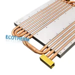
What Is a Heat Sink? Purpose, Types and How It Works
The terms **heat sink** and **heatsink** mean the same thing.
In electronics, both refer to a component used to control temperature in processors, power devices, LED assemblies, and other heat-generating equipment.
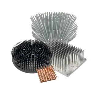
A heat sink is a thermally conductive component that transfers heat from an electronic device to the surrounding air or another cooling medium. Most air-cooled heat sinks have a metal base and fins: the base receives and spreads heat, while the fins provide more surface area for heat to leave the device.
Definition
A heat sink is a passive heat exchanger engineered to transfer thermal energy away from a heat-generating component into a cooler surrounding medium, most commonly air.
Mechanically, it consists of a flat conductive base that interfaces with the heat source and an array of extended surfaces—such as plate fins, pin fins, or flared profiles—that multiply the surface area exposed to the cooling fluid.Without a heat sink, the small external surface area of a modern semiconductor package cannot transfer heat to the surrounding air fast enough.
For example, an exposed processor or ASIC package might offer only 900 mm² to 1,600 mm² of surface area; attaching a properly designed heat sink expands that effective convective interface by 10 to 50 times.
When you use a custom heat sink, a heat pipe heat sink, a Liquid Cold Plate, or even a Vapor Chamber Heatsink, you help your system avoid damage and last longer.
The main points to understand are:
- Heat sinks transfer heat; they do not generate cold air.
- Material, fin geometry, airflow, and mounting work together to determine performance.
- A suitable design must meet the device’s temperature limit in its actual operating environment.
Purpose and Typical Applications
The purpose of a heat sink is to keep a heat-generating component within its intended operating temperature range. By providing a better path for heat to escape, it can help prevent overheating, temperature-related performance throttling, and thermal failure. The benefit depends on the complete cooling system and operating conditions.
The need depends on the component, its electrical load, the enclosure, airflow, and the temperatures around it.
| Application | Typical devices or systems | Typical heat concern | Heat sink’s role |
|---|---|---|---|
| Computing & Data Centers | CPUs, GPUs, AI/ASIC accelerators, FPGA chips, and high-speed optical transceiver modules | Concentrated heat generated during operation can push components toward their temperature limits, especially in densely packed equipment. | Spreads heat from the component over a larger cooling surface so airflow can carry it away. |
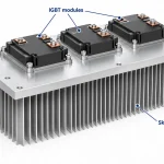
| Power Semiconductors | IGBT modules, SiC/GaN MOSFETs, thyristors, and bridge rectifiers | Switching and conduction losses generate heat, with high local heat flux in demanding operating conditions. | Provides a thermal path from the device to a larger cooling surface and spreads concentrated heat. |
| Power Conversion & Energy Systems | Switched-mode power supplies (SMPS), DC-DC converters, solar and wind inverters, EV onboard chargers, and energy storage system (ESS) power conditioning units | Power conversion losses produce heat in semiconductor devices and other components, particularly under sustained load. | Transfers heat from power components to cooling surfaces or the chassis, helping maintain acceptable operating temperatures. |
| High-Power LED & Optoelectronics | Automotive LED headlights, stadium floodlights, horticultural grow lights, and industrial fiber laser diodes | Heat accumulates near semiconductor junctions. Excessive temperature can reduce LED light output and affect laser wavelength stability. | Conducts heat away from the package or mounting board, helping control junction temperature and maintain optical performance. |
| Industrial Automation & Telecom | Variable frequency drives (VFDs), servo motor controllers, PLC racks, and sealed outdoor 5G remote radio units (RRUs) | Continuous operation, restricted ventilation, and elevated ambient temperatures can cause heat to accumulate inside equipment. | Transfers heat from internal components to available cooling surfaces or the enclosure, supporting temperature control under the intended operating conditions. |
| PCB Regulators & Controllers | Board-mounted voltage regulators, controllers, and other heat-generating electronic components | Local heating may affect the component itself or nearby devices. | Adds a heat-transfer path to surrounding air or a chassis when required; PCB copper can also form part of the cooling path. |
How Does a Heat Sink Work?

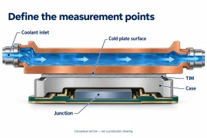
A heat sink moves heat along a continuous path: from an electronic component, through a thermal interface material (TIM), into the heat sink’s base, through its fins, and finally into the surrounding air.
Heat travels through the solid parts mainly by conduction. At the fin surfaces, convection carries it into the air. Nat ural convection relies on warmer air rising and cooler air moving in to replace it; forced convection uses a fan or other airflow source. Radiation also transfers heat, with its contribution varying by surface, temperature, and surroundings. Conduction and convection carry much of the heat in typical electronic air-cooling designs; the balance changes with operating conditions ([heat sink selection methodology]).
The base spreads concentrated heat toward the fins. Poor contact or obstructed air passages can interrupt this path, so the heat sink needs both a sound mechanical interface and a route for warm air to leave.
Why do heat sinks have fins?
Fins expose more surface area to air than a flat base can provide in the same footprint. That extra area can increase heat transfer, provided air can reach and move between the fins. Closely packed fins may impede useful airflow, so fin spacing, height, orientation, and the available airflow need to work together. With natural convection, orientation can also affect how readily warm air escapes; dense fins can reduce effective cooling when they restrict that flow
How do a heat sink and a fan work together?
A fan drives air across or through the fins, increasing air movement near their surfaces and carrying warmed air away. This forced airflow usually lets a design move more heat than natural convection alone under comparable conditions, but the result depends on the fan, fin geometry, and airflow path. The fan does not change the heat sink’s basic job: it helps carry heat away from the fins. A conventional air cooler also cannot cool a component below the local incoming-air temperature without another cooling mechanism.
Some assemblies extend the path with heat pipes or a vapor chamber. These sealed structures use evaporation and condensation to transport or spread heat toward the cooling surface. A heat pipe is useful when heat must travel to a remote fin stack; a vapor chamber spreads heat across a base [two-phase cooling principles]. An integrated [heat pipe cooling module] still needs a surface that can release the heat. A cold plate instead carries heat into a liquid loop, which must transfer it onward at a heat exchanger. Neither arrangement removes the need to reject the heat somewhere.
Heat Sink Types, Materials and Manufacturing
Heat sinks are classified in three separate ways: their cooling mode, material, and construction method. A plate-fin design, for example, can be passive or fan-cooled, aluminum or copper, extruded or assembled from separate fins.
Passive and active heat sinks
A passive heat sink relies on natural convection: air warmed by its surfaces rises and cooler air replaces it. Fin layout and surrounding clearance must allow circulation. Passive designs avoid fan noise, power draw, and moving parts, but performance depends on orientation, enclosure airflow, ambient temperature, and available surface area. There is no universal wattage threshold for choosing passive cooling.
An active heat sink uses a fan or blower to force air across the fins. This can increase heat transfer, while adding power demand, noise, and a part that may need maintenance or replacement. Temperature-controlled fans remain active cooling. Some systems are described as “hybrid” because a fan switches on only when required. Here, that term describes a control strategy rather than a different heat-transfer mechanism. Air must reach the fin passages and have a clear outlet.
Aluminum, copper, and combined materials
Conductivity affects how readily heat spreads from the source through the base and fins, but it does not determine the whole assembly’s performance. Contact resistance, dimensions, fin area, airflow, mounting, and the source interface also matter.
| Material approach | Why consider it | Main consideration |
|---|---|---|
| Aluminum | Lower mass and cost; readily extruded into profiles. | Geometry and airflow must meet the thermal target. |
| Copper | High conductivity can spread heat from a concentrated source. | Greater density and material cost affect mass and budget. |
| Combined | Copper base or insert with aluminum fins can balance heat spreading, mass, and cost. | The material joint adds a step and must provide a reliable thermal path. |
Compare complete designs under their intended conditions. A copper heat sink is not automatically the better system if its mass, geometry, or airflow creates another constraint. Thermal conductivity also varies by alloy and temperature, so use the actual material specification when calculating performance.
How heat sinks are made
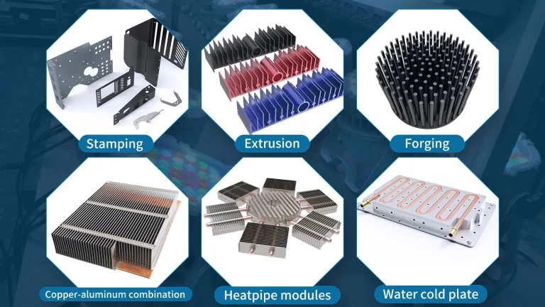
Manufacturing and assembly methods affect fin shape, spacing, height, base thickness, and production cost. Ecotherm’s product range includes the following ten categories, covering heat sinks, cooling assemblies, and precision components.
| Type / Technology | Principle and fit |
|---|---|
| Heat Pipe Cooling Module | Combines heat pipes with a base and cooling fins. The working fluid evaporates and condenses to transport heat, making this approach useful when heat must move from a concentrated source to a larger or remote fin stack. |
| Skived Heat Sinks | Cuts and raises fins directly from an aluminum or copper block. The continuous base-and-fin structure avoids a separate fin-to-base joint and allows dense fin arrangements, while fin spacing must still suit the available airflow. |
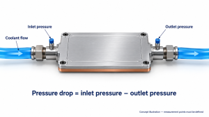
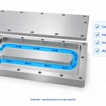
| Liquid Cold Plates | Transfers heat from electronic components into coolant flowing through internal channels or embedded tubes. Suitable for applications where air cooling is constrained; channel design, flow rate, pressure drop, and sealing all affect performance. |
| Vapor Chamber Heat Sink | Uses evaporation and condensation inside a sealed chamber to spread heat across a larger base area. Useful for concentrated hot spots and limited installation space; fins or another cooling surface must release the transferred heat. |
| Cold Forged Pin Fin Heat Sink | Forms the base and pin fins by pressing metal into a die. Pin-fin layouts can accommodate airflow from different directions, while achievable geometry depends on material flow, tooling, and the required dimensions. |
| Extrusion Heat Sinks | Forms a continuous aluminum profile through a shaped die, then cuts it to length. Suitable for repeated cross-sections; secondary machining can add mounting holes, pockets, and other application-specific features. |
| Zippered Fin Heat Sinks | Uses individually formed sheet-metal fins that interlock into a fin stack and connect to a base or heat pipes. Suitable for compact assemblies with controlled fin spacing, particularly where forced airflow is available. |
| Folded Fin Heat Sinks | Folds thin metal sheet into a continuous fin structure and joins it to a base. Provides substantial surface area within a compact volume; fin geometry, airflow access, and joining quality influence thermal performance. |
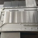
| CNC Machined Thermal Components | Removes material to produce custom bases, plates, channels, and mounting features. Useful for prototypes and application-specific geometry, with machining time, material removal, and dimensional requirements affecting cost. |
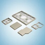
| Stamping Parts | Uses presses and dies to cut and form sheet metal into fins, brackets, plates, and assembly components. Suitable for repeatable production, with tooling, sheet thickness, material, and part geometry determining feasibility and cost. |
What Affects Heat Sink Performance?
A heat sink’s performance depends on how much heat reaches it, how effectively it spreads that heat, and how readily it releases it to surrounding air. The result depends on the complete assembly and its operating conditions, not size or material alone.
Air temperature, airflow, and fin geometry
Start with the air entering the heat sink. Inlet temperature is the relevant ambient condition: air warmed by nearby components or recirculated inside an enclosure leaves less room for cooling than fresh room air. A fan can improve heat transfer, but the airflow that reaches the sink depends on the fan’s operating point and system resistance from grilles, filters, ducts, and nearby components. Free-air fan ratings may overstate flow through an assembled system.
Fin height, thickness, spacing, and direction affect both exposed surface and airflow resistance. More area can help, but tightly spaced fins may restrict flow or leave inner surfaces poorly supplied. Useful fin area depends on both heat reaching the fin surfaces and air being able to carry it away; total geometric area alone does not describe cooling performance. Orientation matters too: natural convection relies on buoyant airflow, while forced-air cooling depends on whether fan flow passes through the fin channels. Dust can block channels over time; enclosure layout can trap hot air or obstruct the inlet and outlet.
Heat spreading and contact
Heat must spread from the source into the sink before the fins can reject it. A small hotspot, uneven mounting pressure, a thin or poorly conducting base, or a poor interface can cause a local temperature rise even when the fins are cool. Check that the base covers the source appropriately and that the mounting surfaces are flat and securely attached.
Thermal interface material (TIM) fills microscopic gaps between surfaces. Paste, pads, and phase-change materials suit different gap sizes, mounting pressures, insulation needs, and assembly processes. There is no universally best choice: a pad may be needed to bridge a gap, while a thin, compliant layer can reduce resistance when surfaces are close and pressure is suitable. Follow component and TIM specifications; excess thickness can add an unnecessary thermal barrier. The different TIM formats exist to meet different interface and assembly needs.
Surface treatment also has a purpose: a finish can protect against corrosion or change radiative heat transfer. Its effect depends on the material, coating, and cooling conditions. A coating on the mounting face may also change the contact interface, so surface finish should be specified as part of the assembly.
Estimate the thermal resistance budget
For a steady-state system where one path dominates through the component case, interface, and heat sink, a useful first estimate is:
Tj ≈ Ta + Q(θJC + θCS + θSA)
The simplified path is:
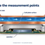
Junction (Tj) → Case (Tc) → Sink base (Ts) → Surrounding air (Ta)
| Symbol | Meaning | Unit |
|---|---|---|
| Tj | Device junction temperature | °C |
| Ta | Local heat sink inlet-air temperature | °C |
| Q | Heat dissipation through the modeled path | W |
| θJC | Junction-to-case thermal resistance | °C/W |
| θCS | Case-to-sink thermal resistance, including the interface | °C/W |
| θSA | Sink-to-air thermal resistance at the stated conditions | °C/W |
Thermal resistance describes temperature rise per watt of heat flow. Q is thermal dissipation, which is not always the equipment nameplate power or a processor TDP figure. Use the datasheet θJC corresponding to the actual cooling surface. This series model follows Texas Instruments’ thermal design guidance, section 6.1; it applies when one heat-flow path dominates. Significant PCB heat flow or transient loads need a more suitable model.
For a hypothetical example, assume:
– Local inlet air: 40°C
– Design junction-temperature target: 100°C
– Heat dissipation: 100 W
– θJC: 0.2°C/W; θCS: 0.1°C/W
The remaining sink-to-air budget is:
θSA,max ≈ (100 − 40)/100 − 0.2 − 0.1 = 0.3°C/W
This is a teaching example, not an Ecotherm product rating. A real selection needs margin for operating variation and validation in the intended enclosure.
In this series model, θCA includes θCS and θSA; it is not the bare heat sink’s resistance. Increasing airflow can lower the achieved θSA, while the allowable budget stays the same if the heat load and temperature targets are fixed. For more detail, see how to calculate heat sink thermal resistance.
How to Choose and Use a Heat Sink
Choose a heat sink for the assembled device and its worst expected operating conditions. A useful first pass is to:
1. Set the thermal target. Estimate the heat actually dissipated during the heaviest workload, then identify the component’s allowable temperature and the highest local inlet-air temperature. Include nearby heat sources and enclosure recirculation.
2. Check the available space and airflow. Record the permitted length, width, height, orientation, and clearance. Determine whether air will move naturally or be driven by a fan, and whether it can pass through the fins and leave the enclosure.
3. Compare thermal performance under matching conditions. Check the temperature or thermal-resistance data at a similar heat load, airflow, orientation, and inlet temperature. A rating from a different test setup may not predict the result in your enclosure.
4. Confirm the interface and mounting. Verify contact area, flatness, mounting pressure, fastener clearance, component strength, and whether the application requires electrical isolation. Select a suitable thermal interface material (TIM) for the gap and assembly requirements.
5. Validate the complete assembly. Run the device at its specified worst-case load and environment, then measure the relevant temperature with a suitable sensor. Compare case temperature with a case limit, or use an appropriate model or device sensor to assess junction temperature. Do not compare a case measurement directly with a junction-temperature limit.
If the geometry is application-specific, send Ecotherm your drawing and thermal conditions for a custom design review.