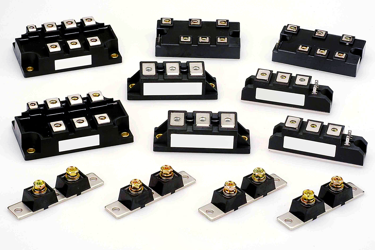
IGBT
Free Custom Design
Free Thermal Analysis
Best Price Guaranteed
24 Hours Feedback
Table of Contents
High-Power IGBT Cooling? We Solve the 500W/cm² Heat Flux Challenge.
From EV Inverters to AI Data Centers, EcoTherm delivers mission-critical liquid cold plates and vacuum-brazed thermal assemblies that keep your junction temperatures under control.
Quick Summary Table”:
| Power Density | Cooling Method | EcoTherm Advantage |
| Low to Medium | Passive / Forced Air | Optimized Fin Geometry |
| High (>300W) | Liquid Cold Plates | Vacuum Brazed / Leak-Free |
| Ultra-High Flux | Vapor Chamber (VC) | Isothermal Uniformity |
Get a Free Thermal Simulation & DFM Review >>>support@ecothermgroup.com
The Critical Role of Thermal Management in IGBT Modules
Thermal management in Insulated Gate Bipolar Transistor (IGBT) modules is the critical engineering process of dissipating massive heat losses generated by the chip into the ambient environment, utilizing passive or active cooling technologies such as custom heat sinks and liquid cold plates. As the core component of power electronic control circuits, an IGBT’s capacity to handle high voltages and currents is strictly limited by its heat dissipation efficiency. Implementing an efficient, stable, and compact cooling system is the fundamental requirement for ensuring safe operation, preventing thermal failures, and extending the lifespan of the power module.
High-Power Trends in EV, Railway, and Renewable Energy
Driven by the rapid advancement of new energy conversion systems, IGBTs have become the dominant power semiconductors in electric vehicle (EV) traction inverters, high-speed railway systems, and renewable energy (wind and solar) applications. The current industry trajectory demands higher power capacities, higher switching frequencies, and greater module integration. Consequently, these devices generate extreme heat flux within highly constrained packaging spaces during high-frequency conduction and switching. Managing this concentrated thermal output is the primary challenge for modern megavolt-ampere (MVA) level power electronics.
The Danger of Overheating: Junction Temperature Limits
More than half of all IGBT power semiconductor failures are directly attributed to thermal mismanagement. Without an effective cooling mechanism, the internal junction temperature of the module will rapidly escalate. If the junction temperature reaches or exceeds its physical limit of 150°C, the device experiences severe performance degradation. Critical parameters deteriorate immediately: switching speeds decrease, the on-state voltage drop increases, current tail times lengthen, and turn-off voltage spikes intensify. Prolonged thermal stress beyond this threshold not only compromises operational reliability but will ultimately result in irreversible thermal runaway, permanently destroying the device and the surrounding system module.
The Critical Role of Thermal Management in IGBT Modules
When evaluating the ROI of a thermal management system, power electronics engineers rely on the well-known “10°C Rule”: for every 10°C reduction in operating junction temperature, the long-term reliability and expected lifespan of the device effectively double. Because the vast majority of IGBT power semiconductor failures are directly attributed to thermal runaway, engineering a highly efficient, low-thermal-resistance cooling system is not optional—it is a mandatory requirement for long-term operational safety.
The Three Pillars of Thermal Resistance Reduction
From a macro thermal-design perspective, engineers must systematically reduce total thermal resistance ($R_{total}$) across three critical domains:
1.Power Module Packaging: Utilizing advanced, high-thermal-conductivity ceramic substrates (such as AlN or Si3N4) to minimize internal volume resistance.
2.Thermal Interface Material (TIM) Optimization: Microscopic air gaps between the power device and the heat sink create massive contact resistance. While filling these gaps with TIM is standard practice, balancing its thermal conductivity with long-term reliability against pump-out effects is a significant engineering challenge.
3.High-Performance Heat Sinks & Cold Plates: This is the most decisive factor. Utilizing optimized forced air or liquid cooling technologies to rapidly transport the heat away from the TIM interface into the ambient environment.
The Ecothermgroup Engineering Advantage: Ecothermgroup tackles these three pillars head-on to provide multidimensional custom solutions. For standard applications, our ultra-flat CNC surface machining minimizes the required TIM thickness, significantly reducing contact resistance. For extreme high-power scenarios, our advanced Direct Liquid Cooling (Baseplateless) technology completely bypasses the TIM bottleneck at the physical level, delivering a truly maintenance-free, ultra-reliable thermal loop tailored to your exact application needs.
Understanding the IGBT Thermal Resistance Network
The Heat Transfer Path: From Chip to Ambient
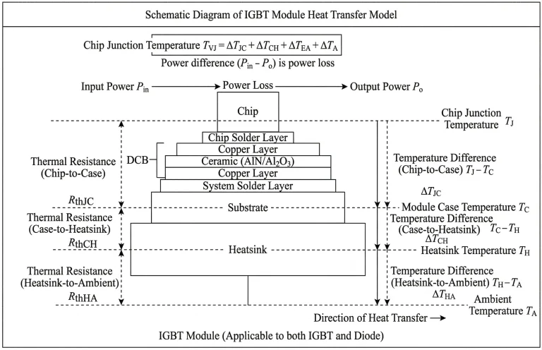
When an IGBT power device is operational, the combination of conduction and switching losses generates a massive amount of concentrated heat at the semiconductor junction. This thermal energy must be continuously drawn away. The standard downward heat transfer path follows this sequence: IGBT Chip → Chip Solder Layer → Direct Bonded Copper (DBC) Ceramic Substrate → System Solder Layer → Copper Baseplate → Thermal Interface Material (TIM) → Heat Sink (or Cold Plate) → Ambient Environment (or Coolant). At each physical transition along this path, the system encounters material volume thermal resistance and interfacial contact thermal resistance.
The Thermal Resistance Formula Explained
The entire heat dissipation process can be precisely modeled using an equivalent thermal circuit. The total thermal resistance Rtotal from the IGBT chip junction to the ambient environment is defined by the following fundamental equation:
Rtotal = Rjc + Rcs + Rsa
In this formula:
Rjc is the thermal resistance from the junction to the case (copper baseplate).
Rcs represents the contact thermal resistance from the case to the heat sink.
Rsa indicates the thermal resistance from the heat sink to the ambient environment or fluid.
Because the internal packaging of modern IGBT modules (like the DBC and chip solder layers) is already highly standardized, significantly reducing Rjc is technologically extremely difficult. Therefore, for thermal engineers and custom heat sink manufacturers, the absolute core of thermal optimization lies in aggressively minimizing Rsa (through advanced heat sink geometries and fluid dynamics) and Rcs (by improving interface management).
The Bottleneck of Thermal Interface Materials (TIM)
In traditional indirect cooling setups, engineers must apply thermal grease or a Thermal Interface Material (TIM) between the copper baseplate and the heat sink to eliminate microscopic air gaps. However, this introduces a critical physical bottleneck. Despite being applied in an ultra-thin layer, the intrinsic thermal conductivity of TIM is remarkably low (typically just a few W/m·K, a fraction of the conductivity of solid aluminum or copper). This TIM layer creates a substantial thermal barrier, severely restricting the rapid transfer of high-density heat flux. Overcoming this specific bottleneck is the exact reason why high-power applications are rapidly shifting toward “Direct Liquid Cooling” architectures, which completely eliminate the copper baseplate and the restrictive TIM layer altogether.
Passive Cooling Technologies for IGBTs (Low to Medium Power)
For low to medium power densities or electronic enclosures with sufficient physical space, passive cooling remains the most cost-effective and reliable thermal management strategy. Passive systems operate without external power sources like fans or pumps, relying entirely on natural convection, conduction, and phase-change principles to dissipate heat into the ambient atmosphere.
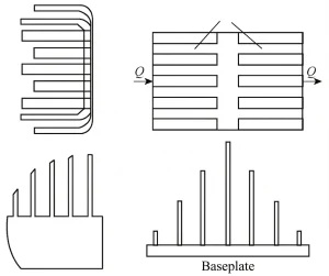
Advanced Fin Heat Sinks
Heat sink fins dissipate the thermal load generated by the IGBT through natural convection. According to Newton’s law of cooling, the convective heat transfer is governed by the formula:
(where Phi is the heat dissipation rate, A is the surface area, h is the convective heat transfer coefficient, and Delta t is the temperature difference).
To maximize Phi within a constrained footprint, engineers must optimize fin geometry. Research indicates that utilizing inverted trapezoidal fins optimizes airflow pathways, yielding a heat transfer coefficient up to 25% higher than standard rectangular fins. Furthermore, integrating highly porous materials like aluminum foam leverages irregular internal micro-channels to exponentially increase the specific surface area, thereby significantly enhancing the natural convection efficiency of the power device.
Heat Pipe and Vapor Chamber (VC) Integration
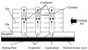
For applications dealing with localized high heat flux, integrating two-phase heat transfer components—such as heat pipes or vapor chambers—into passive heat sinks offers a highly promising solution.
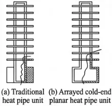
Traditional Heat Pipes vs. Array Flat Heat Pipes
Traditional cylindrical heat pipes are typically embedded into a metal baseplate using thermal grease or mechanical press-fitting, which inherently retains some contact thermal resistance. In contrast, Array Flat Heat Pipe technology utilizes a hollow baseplate design where the substrate and the heat pipes are welded together into a single, seamless cavity.
This architecture transforms the entire baseplate directly into an evaporator, completely eliminating both the conductive resistance of the baseplate itself and the interfacial contact resistance Rcs, resulting in vastly superior transient heat transfer.
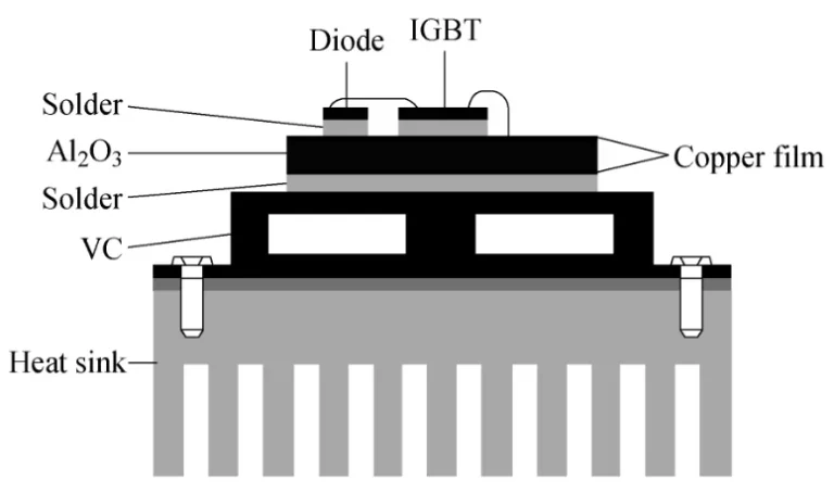
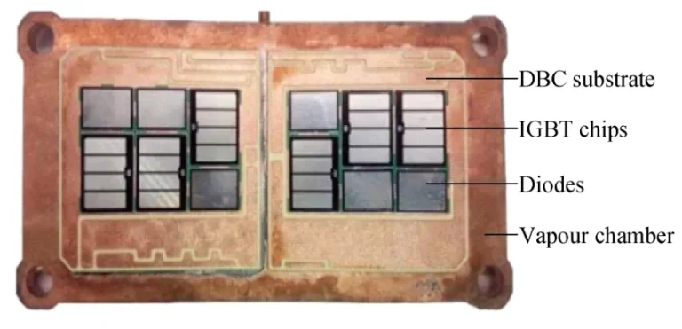
Vapor Chambers (VC) Replacing Metal Baseplates
In highly integrated, compact power electronics, a cutting-edge trend is replacing the heavy traditional copper baseplate entirely with a Vapor Chamber (VC). Unlike conventional heat pipes that transfer heat linearly (1D), a VC rapidly and uniformly spreads concentrated heat loads across a two-dimensional (2D) plane to a larger condensation area. This exceptional temperature uniformity eliminates localized hot spots beneath the IGBT module and drastically reduces maximum thermal stress, significantly extending the operational lifespan of the chip.
Phase Change Material (PCM) Cooling

For applications characterized by intermittent operation or sudden, severe thermal shocks, heat sinks based on Phase Change Materials (PCM) provide an excellent passive thermal buffering mechanism. When the IGBT experiences a thermal spike, the PCM core (such as paraffin wax) absorbs massive amounts of latent heat during melting, effectively capping the junction temperature below critical thresholds. The heat is then slowly released into the environment during the device’s off-cycle. To overcome the inherently low thermal conductivity of pure PCMs, advanced designs embed innovative tree-shaped metal structures or high-conductivity graphite foams within the PCM enclosure. These internal structures create a rapid thermal superhighway, instantly dispersing the heat flux deep into the PCM core.
Active Cooling Technologies: The Standard for High-Power IGBTs
As IGBT power semiconductor modules advance into the megavolt-ampere (MVA) range with high-frequency operation, natural convection completely fails to meet the extreme thermal demands. To prevent thermal runaway, active cooling technologies—utilizing external driving forces such as fans or liquid pumps to force convection—have become the undisputed industry standard for high-power electronics.
Forced Air Cooling: Capabilities and Limitations
By utilizing optimized air ducts and high-pressure industrial fans, forced air cooling accelerates the airflow across heat sink fins, increasing the heat dissipation capacity by 5 to 12 times compared to passive natural cooling. However, forced air cooling presents severe physical limitations when applied to ultra-high power densities:
Bulky Footprint & Routing Issues: High-power air cooling requires massive heat sink volumes and complex air duct designs, directly conflicting with the modern trend of miniaturization in power electronics.
Acoustic Noise & Maintenance: High-RPM fans generate significant acoustic noise and are highly susceptible to physical blockages in dusty or harsh environments, significantly reducing system reliability.
The Thermal Ceiling: When pushing into the MVA power range (e.g., utility-scale wind converters), the low specific heat capacity of air simply cannot absorb and transport the transient heat spikes fast enough.
Liquid Cooling (Water Cooled IGBTs): The Ultimate Solution for High-Power Modules
When IGBTs operate at high frequencies, the continuous heat loss drives a rapid temperature rise. Industry statistics reveal that over half of all IGBT device failures are caused by thermal-related faults. Particularly when equipment power scales to the megavolt-ampere (MVA) level, traditional forced air cooling faces insurmountable physical hurdles regarding duct design, air pressure requirements, and acoustic noise. To overcome these limits, liquid cooling technology—specifically water cooled IGBT solutions—has become the preferred choice for high-power thermal management, offering heat transfer capacities that vastly outperform air.
Indirect vs. Direct Liquid Cooling (Pin Fin Cold Plates)
When engineering a water cooled IGBT system, the industry is rapidly transitioning from “indirect” to “direct” cooling architectures. This transition highlights a core manufacturing capability of Ecothermgroup:
Indirect Liquid Cooling (With Baseplate): Traditional IGBT modules feature a heavy copper baseplate. Mounting them requires a layer of Thermal Interface Material (TIM) between the baseplate and the liquid cold plate. As established earlier, this TIM layer creates a severe bottleneck in thermal resistance.
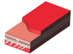
Direct Liquid Cooling (Baseplateless Design): Advanced direct liquid cooling completely eliminates the heavy copper baseplate and the restrictive TIM layer. Instead, a metallic structure featuring a Pin Fin array is integrated directly beneath the DBC ceramic substrate, allowing the liquid coolant to interact almost directly with the heat source. By utilizing precision-machined or forged pin fin cold plates, the system induces aggressive fluid turbulence while maximizing the internal wetted surface area. Engineering data confirms that this direct liquid cooling architecture dramatically reduces the total thermal resistance ($R_{total}$) by 20% to 40%, while ensuring exceptional temperature uniformity across the semiconductor die.
How to Choose the Right IGBT Cooling System (Passive vs. Active)
Selecting the optimal IGBT cooling system depends on the module’s power density, available packaging space, and budget constraints. The following table provides a clear engineering comparison of the four mainstream thermal technologies:
Table: Comparison of IGBT Cooling Technologies
| Cooling Technology | Typical Power Range | Typical Thermal Resistance (Rth) | System Cost | Best Applications |
| Forced Air Cooling | Low – Medium (< 100 kW) | Higher (0.05 – 0.2 °C/W) | Low | Small inverters, standard industrial drives |
| Heat Pipe / VC | Medium (High localized heat flux) | Moderate (0.02 – 0.08 °C/W) | Medium | Highly integrated power electronics, compact enclosures |
| Indirect Liquid Cooling | High (100 kW – 1 MW) | Lower (0.01 – 0.03 °C/W) | High | Large commercial inverters, legacy EV controllers |
| Direct Liquid Cooling | Ultra-High (> 1 MW / MVA level) | Extremely Low (< 0.01 °C/W) | Higher | Modern EV traction inverters, core wind/solar converters |
Partner with Ecothermgroup for Custom IGBT Thermal Solutions
As a professional custom heat sink manufacturer, Ecothermgroup is dedicated to solving thermal bottlenecks in high-density electronics. We don’t just understand advanced thermodynamics; we possess the manufacturing capabilities to turn theories into highly reliable physical products.
Thermal Simulation, Prototyping, and Mass Production
We provide B2B clients with an end-to-end service loop from conceptual design to mass production:
Computational Fluid Dynamics (CFD) Simulation: We optimize micro-channel and pin fin geometries before production, accurately predicting pressure drop ($\Delta P$) and thermal distribution to minimize R&D trial-and-error costs.
Rapid Prototyping: Utilizing high-precision CNC machining and vacuum brazing, we deliver validation-ready prototypes swiftly.
Scalable Mass Production: Operating under the strict IATF 16949 quality management system, we guarantee scalable manufacturing with helium leak-tested, zero-defect liquid cold plates.
Frequently Asked Questions (FAQs) About IGBT Cooling
Why is direct liquid cooling better than indirect for IGBTs? Direct liquid cooling completely eliminates the traditional copper baseplate and the Thermal Interface Material (TIM) layer. By removing the primary contact thermal resistance and allowing the coolant to interact directly with the heat source, it reduces overall thermal resistance by 20% to 40% and drastically improves temperature uniformity.
How does a Vapor Chamber improve IGBT thermal management? Unlike standard heat pipes that transfer heat in one dimension (1D), a Vapor Chamber spreads concentrated heat rapidly across a two-dimensional (2D) plane. This effectively eliminates localized hot spots beneath the chip, substantially lowering maximum thermal stress and extending the IGBT’s operational lifespan.
What is the maximum junction temperature for an IGBT? The maximum safe operating junction temperature for most industrial-grade IGBTs is limited to 150°C (though some advanced SiC modules can reach 175°C). Exceeding this critical threshold causes severe performance degradation, such as increased voltage drops and tail currents, ultimately leading to irreversible thermal runaway and device destruction.
IGBT WITH ECOTHERM ONE STOP THERMAL SOLUTIONS
Heatsinks play an integral role in the thermal management of power electronics such as Insulated-Gate Bipolar Transistors (IGBTs). These heat dissipation devices help to prevent overheating and prolong the lifespan of IGBTs, which are commonly used in a variety of applications including motors, renewable energy, and electric vehicle (EV) powertrain systems.
IGBTs are semiconductor devices used to switch high voltage and current levels in industrial and consumer electronics applications. The problem arises when the IGBTs operate at high power levels. The IGBTs function on the principle of switching and thus generate heat during its operation due to its internal power losses in the form of conduction and switching losses. This increased temperature, if not managed effectively, can result in thermal runaway and eventual device failure. Thermal runaway in IGBTs can cause a number of issues like degradation of performance, loss of efficiency and unwanted shut down, leading to excessive costs and downtime.
RELATED PRODUCTS ABOUT PROFESSIONAL HEATSINK
Heatpipe Cooling Module
Skived Heat Sinks (900mm*3meter)
Liquid Cold Plates
Vapor Chamber Heat Sink
Cold Forged Heat Sink(Pin Fin)
Extrusion Heat Sinks
Zippered Fin Heat Sinks
Folded Fin Heat Sinks
CNC Machining Parts
Stamping Parrs
High Power Cooling Solutions For Customized Projects
Our customized cooling solution can be tailored to your project requirements, delivering the highest level of cooling efficiency under specific demands.
Crafting Custom
Heatsinks for Your Needs
Feel free to get in touch with us to discuss your project specifics, request quotes, or inquire about our capabilities.
Our team of experts is dedicated to delivering top-notch quality and precision in every heatsink we produce
Free 24 Hours Feedback Thermal Analysis
Focus On Customized Cooling Solutions
22 Years Experiences OEM Factory
Send Your Drawing For Evaluation
CONTACT ECOTHERM
Please contact us to get in touch with our experts. We can provide design services for your project and thermal simulation services within 24 hours.
Note: Ecotherm does not provide a standard thermal model.We focus on providing professional design and production services for your new projects