Wavy vs. Straight Skived Heat Sinks: Which Fits Your Cooling Design?
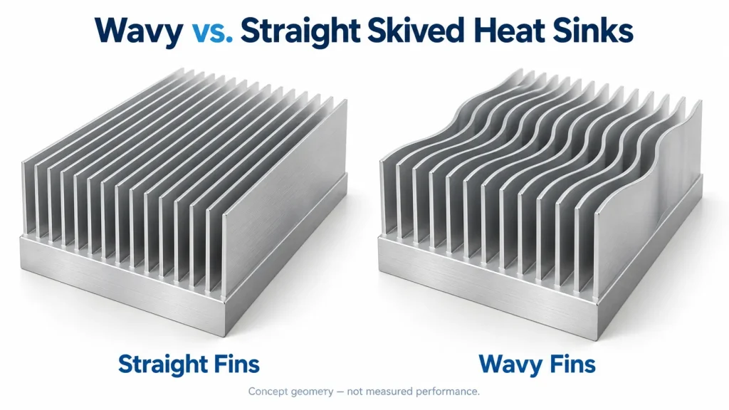
A wavy skived heat sink is worth comparing with a straight-fin design when the cooling target is difficult to meet within the available space. It is not automatically the better option. The useful question is whether the proposed wave profile improves temperatures under the airflow, installation and manufacturing conditions of your project.
For an inverter, motor drive or industrial power supply, that decision needs more than a photograph or a surface-area claim. Start with a defined straight-fin baseline, identify what the wavy version changes, and compare both against the same project requirements.
This guide focuses on air-cooled skived fins with a repeated lateral wave. It does not transfer performance figures from liquid cold plates, folded-fin heat exchangers or unrelated wavy-fin studies to a custom skived part.
What Changes When a Skived Fin Becomes Wavy?
Skiving forms fins by slicing and raising metal that remains attached to the base. In a monolithic skived heat sink, the fins and base form a continuous structure. Eaton’s skiving overview describes this process and the geometry constraints involved.
The distinction here is the fin’s path when viewed from above:
- A straight fin follows a direct line along the channel.
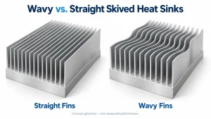
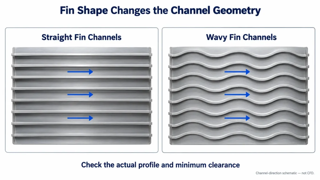
- A wavy fin follows a repeated lateral curve, changing the channel geometry.
This is different from a serrated top edge or unintended bending of a straight fin. Patterned skived fins, including wavy plan-view profiles, are documented in a published heat sink design. That establishes a geometry example, not a comparative performance result.
“Wavy” alone is therefore an incomplete specification. Two products can both use the term while having different wave amplitudes, wavelengths, channel clearances and fin arrangements.
The integral fin-to-base construction also does not mean zero total thermal resistance. Heat still passes through the device interface, the base and the fins before reaching the air. Changing the fin path addresses only part of that route.
Compare Heat Transfer and Airflow Resistance Together
For the same fin count, height and projected length, a curved path can add fin surface area. Whether that extra surface improves the complete cooler depends on how effectively air reaches it and how heat travels through the structure.
Advanced Thermal Solutions discusses the tradeoff between fin geometry, heat transfer and flow resistance. The comparisons cover particular geometries and operating conditions; they do not establish a universal advantage for every wavy skived heat sink.
| Review point | Straight skived fins | Wavy skived fins |
|---|---|---|
| Channel shape | Direct path along the fins | Repeated lateral changes in direction |
| Available surface | Set by height, length, thickness and fin count | Also influenced by the wave profile |
| Flow resistance | Depends on channel dimensions and installation | Must be evaluated for the specified curves and clearance |
| Drawing definition | Straight-fin dimensions and layout | Those dimensions plus the waveform and neighboring-fin arrangement |
Do not assume that every curved channel creates turbulent flow or that additional surface always compensates for pressure loss. The net result must be evaluated for the actual design.
Changing flow resistance can also change the delivered airflow. A fan operates where its pressure-flow curve meets the system resistance curve, as explained in ebm-papst’s fan guidance. Using the same fan does not ensure the same airflow through two different fin arrays.
An initial electronics cooling airflow estimate helps define the required flow. It still needs to be checked against the fan, enclosure restrictions and candidate heat sink.
When Is a Wavy Design Worth Evaluating?
A useful starting point is a straight-fin design that fits mechanically but leaves insufficient thermal margin. If the fin profile and airflow arrangement can still change, a wavy candidate gives the team another geometry to evaluate within that space.
First identify the dominant limitation. Is the temperature rise mainly associated with the device interface, heat spreading through the base, or heat transfer from the fins to the air? ATS’s heat sink comparison guidance distinguishes these parts of the thermal path. A fin-profile change may deliver little benefit if the main constraint is elsewhere.
For a drive or power converter, review the hottest module location rather than only an average base temperature. A lower average does not necessarily resolve the limiting component temperature.
Keep the straight-fin option if it meets the requirements and the proposed change has no demonstrated project benefit. A wavy profile is not an upgrade by definition.
Also state the constraints that the comparison must respect: permitted fan settings, acoustic targets, maintenance access and the operating environment. Do not infer a dust-retention or cleaning advantage from the fin shape alone. Review the actual channel geometry and maintenance method.
If the temperature budget is not yet defined, establish the required heat sink thermal resistance before choosing a more elaborate profile.
Specify the Wave Profile, Not Just “Wavy Fins”
A supplier needs a defined shape, not an instruction to make the fins “more wavy.” Show the profile in the plane perpendicular to fin height.
For a sinusoidal design, define amplitude from the mean line to a crest, and wavelength between repeating crests. For another shape, provide a profile drawing or coordinates. Show how neighboring fins align or offset relative to one another; do not assume every design uses the same phase arrangement.
Include these details in the drawing review:
- Free channel clearance: the minimum clear distance between fin surfaces, not merely the fin center-to-center pitch.
- Fin geometry: thickness, height, profile, projected flow length and fin count.
- Base and mounting: base thickness, overall footprint, contact regions, mounting holes and fin-free areas.
- Assembly access: fastener, connector and tool keep-outs around the fin field.
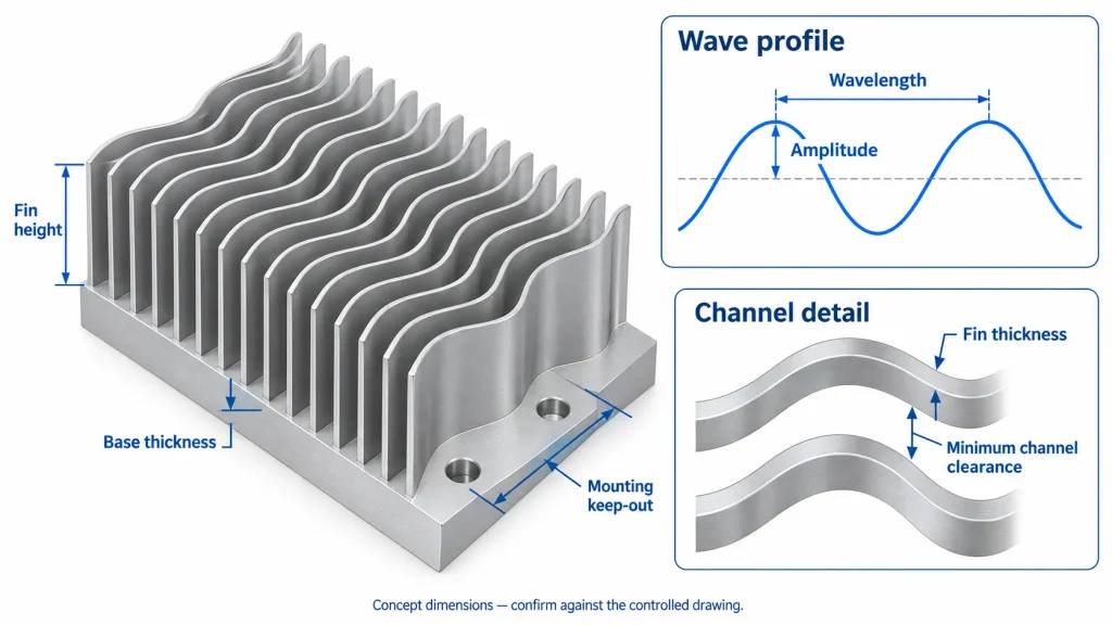
Define how minimum clearance is to be measured, particularly where curved surfaces approach one another. Keep designed waviness separate from unintended fin deformation. Agree on handling, deburring and inspection requirements rather than borrowing a tolerance from an unrelated product.
Separate fixed requirements from dimensions open to review. Height, thickness, spacing, waveform and flow length interact during manufacturing; individually published limits should not be assumed achievable together. Eaton notes that fin thickness, flow length and height affect the force required to form skived fins.
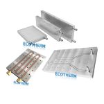
Ecotherm’s wavy skived heat sink options provide a starting point for discussing the structure. The actual profile and machining features still require drawing-specific confirmation. Record any accepted changes on a controlled revision.
Test Straight and Wavy Samples on a Fair Basis
Decide what the comparison is intended to answer before ordering samples.
To isolate the fin geometry, keep the material, base footprint and thickness, heat-source map, interface material, inlet temperature, orientation, duct conditions and measured airflow consistent. Record differences that remain, such as fin count, mass or total surface area. Otherwise, an apparent profile benefit may come from another design change.
To compare installed cooling, use the intended fan, controls and enclosure. Measure the resulting flow rather than forcing an assumption that both candidates receive the same airflow. Assess the relevant device temperatures and any specified noise or fan-power limits.
These are different comparisons. Fixed-flow results describe performance at a controlled flow condition; installed results show what each assembly achieves with the available air-moving system.
Keep measurement references consistent. Base temperature, module case temperature and semiconductor junction temperature are not interchangeable. Identify sensor locations and the temperature reference used for any reported thermal resistance. ATS’s heat sink testing guidance also explains why ducted and unducted results can differ.
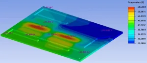
Ask for the setup description and measured results, not just a statement that one sample is cooler. If a simulation supports the selection, identify its assumptions and the sample measurements used to check it.
To discuss custom skived heat sink manufacturing, send Ecotherm the current drawing, candidate wave profile and the cooling issue you need to resolve. Include the heat-source layout and available fan or enclosure details if you have them. Email support@ecothermgroup.com; a sketch with clearly marked unknowns is enough to start the discussion.