Fins in a heat sink boost surface area, allowing you to dissipate more heat and keep devices cool. You benefit from this design because experiments show that the best fin configuration can increase heat dissipation by almost 13% compared to a flat surface. The arrangement and shape of heat sink fins, such as those in a skived heatsink or heatpipe heatsink, dramatically influence cooling results. With a custom heatsink, you can access tailored solutions and free analysis to ensure optimal performance for your specific needs.
Key Takeaways
- Heat sink fins increase surface area to help devices release heat faster and stay cool.
- Different fin shapes and arrangements affect how well heat moves away from your device.
- Materials like aluminum and copper impact heat transfer, cost, and weight of fins.
- Proper fin spacing and thickness balance airflow and heat dissipation for best results.
- Custom cooling solutions offer tailored fin designs and free analysis to improve performance.
- Advanced simulations and quality inspections ensure reliable and efficient heat sinks.
- Choosing the right fins prevents overheating and extends the life of your electronics.
- Optimized fins reduce energy use and support greener, more efficient cooling systems.
Heat Sink Fins and Their Role
Surface Area and Heat Dissipation
How Fins Increase Surface Area
You rely on heat sink fins to maximize the surface area available for heat transfer. By adding fins, you expose more of the heat sink to the surrounding air, which allows more heat to escape from your device. The greater the surface area, the more efficiently your heat sink can dissipate heat. Computational fluid dynamics simulations show that heat sinks with perforated pin fins outperform solid fins, with tapered perforations boosting system performance by up to 6.1%. Designs that use converging perforations further enhance heat dissipation while managing airflow resistance.
You can see the impact of fin geometry and arrangement in several ways:
- Taller fins increase the effective surface area and improve heat transfer.
- Innovative designs, such as split fins or variable-height fins, promote fluid mixing and boost thermal performance.
- Optimal fin spacing reduces thermal resistance, but spacing that is too wide can lower the heat transfer coefficient.
- Inclined or interrupted fins can improve heat dissipation by up to 24% compared to conventional straight fins.
These improvements depend on the specific geometry, spacing, and flow conditions of your application. When you choose a custom cooling solution, you can tailor these parameters to match your device’s requirements, ensuring maximum efficiency.
Mathematical models help you understand and optimize these effects. For example:
Dimensional analysis and the Buckingham Pi theorem simplify complex heat transfer problems, letting you predict how changes in fin geometry and surface area will affect cooling performance.
Convection and Airflow
You depend on convection to move heat away from the fins and into the air. The shape and arrangement of fins directly influence how air flows around the heat sink, which affects how quickly heat dissipates. For example, straight plate fins provide a basic airflow path, while louvered or wavy fins create turbulence that increases the heat transfer coefficient. Pin fins with conical or elliptical shapes reduce airflow resistance and pressure drop, making them ideal for forced convection systems.
Experimental studies show that even small changes in fin geometry can have a big impact. A slight taper in the fins reduces thermal resistance, while wavy or interrupted fins reset the thermal boundary layer, improving heat transfer. Adding wings to pin fins increases turbulence and surface area, resulting in up to 47% better heat transfer, though it may also increase pressure drop.
Proper fin spacing and height are crucial. Too little spacing restricts airflow, while too much reduces the available surface area. Taller fins increase both surface area and the face area exposed to airflow, but they also add weight and cost. Custom cooling solutions allow you to balance these factors for your specific application, ensuring optimal airflow and heat dissipation.
Tip: Efficient heat sink fins not only improve device performance but also reduce the need for energy-consuming fans or air conditioning. This energy efficiency leads to a smaller carbon footprint and supports a greener approach to electronic cooling.
Fin Design
Shape and Arrangement
You can boost your device’s cooling performance by choosing the right fin shape and arrangement. The geometry of the fins determines how efficiently heat moves away from your components. You should consider how airflow interacts with each design to maximize heat dissipation.
Pin Fins
Pin fins offer flexibility for compact electronics. You see them in many high-performance heat sinks because they create multiple pathways for air and heat. Round pin fins excel when you need to manage higher pressure drops and pumping power. Staggered arrangements of pin fins generally outperform inline layouts, giving you better heat transfer. You can select elliptical pin fins for low-pressure drop and efficient cooling.
- Perforated pin fins outperform solid fins in heat dissipation.
- Square perforations increase heat transfer by 44% in natural convection.
- Circular perforations improve heat transfer by 42% in forced convection.
- Circular perforated fins outperform square and triangular perforations by up to 6.4% in forced convection.
- Staggered elliptical fins offer optimal performance for low-pressure drop and pumping power.
- Inclined fins, especially with V-type arrangements, enhance heat transfer rates and improve temperature distribution.
Tip: You can request custom pin fin designs with tailored perforation shapes and arrangements. This approach helps you solve unique cooling challenges in compact devices.
Straight Fins
Straight fins provide a simple and effective solution for many cooling applications. You often see them in heat sinks for computers and LED lighting. These fins create a direct path for airflow, which helps move heat away from the base. You can adjust the height and spacing to match your device’s airflow and thermal requirements.
- Microchannel heat sinks with grooves and ribs improve heat transfer.
- Rectangular ribs work best at lower Reynolds numbers (below 500).
- Elliptical ribs perform better at higher Reynolds numbers.
- Hybrid designs like the F2/S2 heat sink combine straight and pin fins for compact, power-efficient cooling.
You can choose straight fins for easy manufacturing and reliable performance. Custom solutions allow you to optimize fin spacing and height for your specific needs.
Material Choices
You must select the right material for your heat sink fins to balance cost, weight, and thermal performance. Aluminum and copper are the most common choices. Each material offers distinct advantages.
Aluminum fins give you a lightweight and cost-effective solution. You benefit from easier manufacturing and good corrosion resistance. Copper fins provide superior thermal conductivity and durability, but they cost more and add weight. You can request custom cooling systems with the material that best fits your budget and performance goals.
Note: You can work with experts to select the ideal fin shape, arrangement, and material. Custom cooling solutions help you achieve reliable thermal management for any application.
Heat Sink Fins and Performance
Thermal Efficiency
You can maximize the thermal efficiency of your cooling system by carefully selecting the thickness and spacing of your heat sink fins. When you decrease fin thickness, you increase the total surface area available for heat transfer. This change improves melting uniformity in phase change material (PCM)-based heat sinks by 52% and enhances thermal conductance by 38%. As a result, you see a 15% increase in reliable operating time, which means your device can run longer without overheating. However, you must balance fin thickness and height. If you make fins too thin and tall, heat transfer at the tips becomes difficult, which limits efficiency gains.
Fin spacing also plays a crucial role. You should keep spacing above 4mm to allow smooth natural convection. If you increase spacing too much, you reduce the number of fins and the total surface area, which can lower overall performance. The best results come from optimizing both thickness and spacing to match your device’s airflow and heat load.
When you evaluate thermal efficiency, you can use several key metrics:
- Time to reach set point temperature (SPT): Measures how quickly your heat sink stabilizes.
- Storage Ratio: Shows how much thermal energy your system can store.
- Energy Storage Rate: Indicates how fast your system absorbs heat.
- Melting Fraction and Enhancement Ratio: Quantify improvements in phase change and heat transfer.
You can also look at the following table to understand how different factors affect performance:
You can request custom cooling solutions that use advanced fin designs, such as pin fins or micro-fins, to further boost efficiency. New technologies like 3D printing and fluid topology optimization allow you to create complex geometries that maximize heat dissipation while minimizing weight and material use.
Tip: Custom cooling systems let you fine-tune every aspect of your heat sink fins, ensuring you get the best thermal performance for your specific application.
Device Reliability
You depend on effective heat sink fins to keep your devices running reliably over time. By increasing surface area and improving heat dissipation, you lower the operating temperature of sensitive electronic components. This reduction in temperature decreases thermal stress, which helps prevent premature failure and extends the lifespan of your equipment.
You can choose from a variety of fin types—straight, pin, laminar, or even hybrid designs—to match your device’s cooling needs and space constraints. The right combination of thickness, height, and spacing ensures optimal airflow and cooling performance. High thermal conductivity materials like aluminum and copper transfer heat efficiently, supporting stable operation even in demanding environments.
- Proper fin design prevents overheating and maintains thermal balance.
- Innovations such as micro-fins, nanomaterials, and hybrid cooling systems address the needs of miniaturized and high-power electronics.
- Custom solutions allow you to adapt to new challenges, whether you work in electronics, automotive, aerospace, or telecommunications.
When you invest in a tailored cooling system, you protect your devices from heat-related failures and ensure long-term, stable performance.
Custom Solutions
Free Analysis Services
You gain a significant advantage when you choose custom cooling solutions. Manufacturers offer free thermal analysis and simulation using advanced 3D modeling and computational fluid dynamics (CFD) tools. You can submit your device drawings for a tailored thermal review. Engineering teams provide design feedback, thermal management assistance, and support for design changes. You access fully equipped labs for design validation, testing, and inspection. These services help you achieve optimal thermal performance for your specific device.
- Free thermal analysis and simulation
- Custom design reviews and engineering support
- Lab validation and inspection
- Improved device reliability and efficient space utilization
- Reduced manufacturing costs and timely cooling solutions
Tip: You can solve complex cooling challenges by leveraging these complimentary services. You receive expert guidance from the initial concept to the final product.
Simulation and Drawings
You benefit from simulation and drawing services that streamline the design process. Thermal analysis predicts heat dissipation efficiency by considering material properties, surface area, airflow, and contact resistance. CFD simulations model airflow and heat transfer around your heat sink, allowing you to visualize thermal behavior before building a prototype. Finite Element Analysis (FEA) identifies temperature distribution and pinpoints inefficiencies. Engineers use these tools to optimize geometry and make informed decisions.
- CFD and FEA predict thermal performance and optimize geometry
- Analytical modeling provides quick design scenarios and validates simulation results
- Direct CAD import ensures precise simulation of heat sink features
- Accurate meshing captures heat spreading and airflow between fins
- Simulation reduces the need for costly prototypes and speeds up development
A recent case study showed a 14% improvement in LED heat sink performance after simulation and physical validation. Advanced simulation tools, including machine learning models, can predict thermal parameters with up to 98% accuracy. You save time and money while ensuring your cooling solution meets demanding requirements.
Quality Inspection
You receive products that meet the highest standards of reliability. Every custom heat sink undergoes 100% full inspection before shipment. Manufacturers apply rigorous quality protocols, including burn-in testing, helium leak detection, and performance validation. Dimensional measurements ensure precise construction. ISO 9001:2015 certification, statistical process control, and first article inspection guarantee consistent quality.
Note: You can trust that every product has passed strict inspection and validation. This commitment to quality ensures your cooling system performs reliably in any environment.
Custom cooling solutions outperform standard heat sinks in specialized applications. You benefit from optimized material usage, lower inventory costs, shorter assembly times, and reduced shipping expenses. Precision cutting with tolerances as tight as ±0.2mm enables integration into demanding fields such as aerospace, medical, and power electronics. You receive a solution precisely matched to your requirements, backed by expert support and thorough quality assurance.
Choosing the Right Heat Sink Fins
Selection Factors
You need to consider several important factors when selecting heat sink fins for your application. The right choice ensures your device stays cool and operates reliably. Start by looking at the type of heat sink. You can choose from stampings, extrusions, bonded or fabricated fins, castings, and folded fins. Each type offers unique manufacturing methods and performance characteristics. For example, extruded fins allow for complex shapes, while bonded fins support higher aspect ratios, increasing cooling capacity without adding bulk.
Material selection plays a key role. Aluminum gives you a lightweight, cost-effective option. Copper provides higher thermal conductivity but adds weight and cost. Fin configuration also matters. Straight, pin, and zigzag fins each suit different airflow patterns and space constraints. You should match the fin shape to your cooling method—straight fins for natural convection, pin fins for multidirectional airflow, and louvered fins for forced convection.
Environmental conditions affect your decision. High altitude reduces air density, which lowers cooling performance. You must apply derating factors to thermal resistance values in these cases. Consider temperature swings, humidity, dust, and vibration. Choose robust construction and appropriate ratings for harsh environments.
To avoid common mistakes, always optimize fin shape, thickness, spacing, and height. Ignoring airflow patterns or underestimating thermal loads can lead to poor heat dissipation. Use thermal analysis tools and simulations to refine your design. Prototyping and testing help you achieve the best results.
Tip: Select fin shapes that match your airflow and cooling needs. Balance fin spacing to maximize surface area while minimizing resistance. Always consider manufacturing capabilities and use quality thermal interface materials.
Solving Cooling Challenges
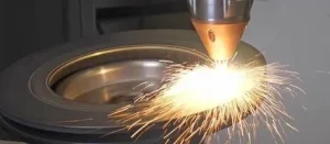
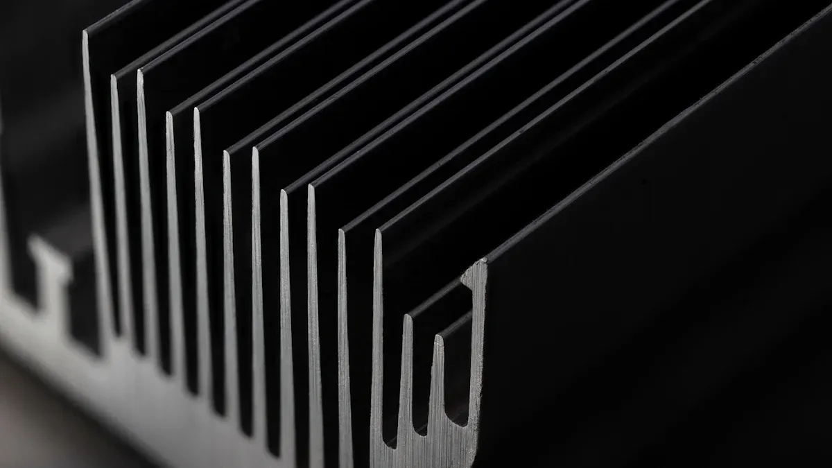
You can solve unique cooling challenges by leveraging custom heat sink fin designs. Engineers use advanced manufacturing methods like skiving, extrusion, and bonding to tailor fin geometry for your specific needs. The skiving process, for example, slices thin, tall fins directly from a solid block, creating a seamless, one-piece heat sink. This method eliminates thermal resistance from joints and allows precise control over fin height, thickness, and spacing.
The table below compares common fin types and their performance:
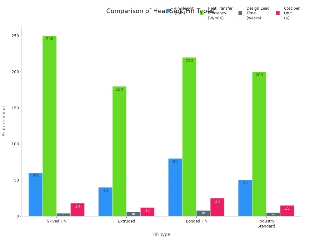
Custom solutions let you adapt fin geometry to tight spaces and high-density layouts. For example, engineers designed skived fins 60 mm tall with 1.5 mm spacing for a big data server, reducing temperatures by 15°C compared to extruded fins. In wind power inverters, custom copper skived fins dropped temperatures by 17°C, boosting reliability. CNC machining and friction stir welding ensure tight tolerances and structural integrity. Rapid prototyping speeds up the process, so you get tailored solutions quickly.
Note: When you work with a company that offers custom cooling systems, you receive expert support from design to production. You can optimize every aspect of your heat sink fins to meet your device’s unique thermal demands.
You rely on heat sink fins to maximize heat dissipation and protect your devices from overheating. Recent research shows that optimized fin designs can lower temperatures by up to 39°C and reduce material usage by 21%. Custom cooling solutions give you access to free analysis, advanced simulations, and tailored designs that improve efficiency and reliability.
- Custom analysis and design services help you solve unique cooling challenges.
- You benefit from expert support, high-performance materials, and innovative fin configurations.
Choose custom cooling systems to ensure your devices stay safe and perform at their best.