3D Vapor Cooling vs. Traditional Vapor Chambers: Thermal Performance Analysis
Introduction:
High-power electronics, including AI processors, IGBTs, and dense power modules, are rapidly breaching traditional thermal management limits. As power densities scale, the standard vapor chamber (VC) frequently encounters severe performance bottlenecks under high heat flux conditions.
When heat flux exceeds a critical threshold, the fundamental question arises: is a 2D vapor chamber still sufficient? For thermal engineers dealing with concentrated hot spots that outpace planar spreading capabilities, the answer is often no. The engineering solution to this thermal bottleneck is the 3D vapor chamber, a next-generation cooling architecture built for volumetric heat transport.
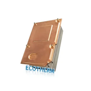
What Is a Traditional Vapor Chamber (2D VC)?
Physics-Based Explanation
A traditional vapor chamber operates on the principle of phase-change heat transfer. When the heat source applies power to the evaporator zone, the internal working fluid vaporizes. This vapor absorbs latent heat, spreads across the lower-pressure cavity, and reaches the condenser region where it reverts to a liquid. The capillary action of the internal wick then returns the liquid to the heat source. In a 2D VC, this heat spreading model is strictly planar (in-plane heat spreading).
Working Principle
Heat input causes the working fluid to evaporate
Vapor spreads laterally across the chamber
Condensation occurs in cooler regions
Liquid returns via capillary action
This process enables efficient in-plane heat spreading, making it widely used in compact thermal systems.
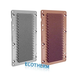
Structural Characteristics
Single Cavity: Operates within a flat, sealed envelope.
Planar Wick Structure: Utilizes flat sintered copper powder, mesh, or grooved wicks.
Heat Spreading Path: Restricted to the X-Y plane before transferring heat to the attached fins or heat sink.
Typical Applications
Laptop and mobile device cooling
GPU heat spreaders
Telecom and networking equipment
What Is a 3D Vapor Chamber?
Core Structural Innovations
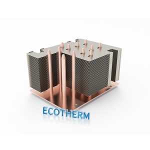
A 3D vapor chamber breaks the planar limitation by integrating vertical structures directly into the base cavity. These internal additions typically consist of vertical vapor columns, micro heat pipes, or a 3D pillar/wick structure. The critical distinction is the shift from 2D planar spreading to true 3D volumetric thermal transport.
Upgraded Working Mechanism
In a 3D architecture, vapor does not merely spread laterally; it is transported rapidly along the vertical axis directly into the cooling fins. This drastically shortens the condensation path and provides a more efficient, gravity-assisted (or gravity-agnostic, depending on the wick) liquid return path to the evaporator.
Key Structural Difference
Unlike standard designs, a 3D vapor chamber introduces:
Vertical vapor pathways
Internal pillar or column structures
Integrated micro heat pipe-like channels
This allows heat to move in X, Y, and Z directions, not just across a flat plane.
Upgraded Working Mechanism
In a 3D architecture, vapor does not merely spread laterally; it is transported rapidly along the vertical axis directly into the cooling fins. This drastically shortens the condensation path and provides a more efficient, gravity-assisted (or gravity-agnostic, depending on the wick) liquid return path to the evaporator.
Physics-Based Explanation
A traditional vapor chamber operates on the principle of phase-change heat transfer. When the heat source applies power to the evaporator zone, the internal working fluid vaporizes. This vapor absorbs latent heat, spreads across the lower-pressure cavity, and reaches the condenser region where it reverts to a liquid. The capillary action of the internal wick then returns the liquid to the heat source. In a 2D VC, this heat spreading model is strictly planar (in-plane heat spreading).
2D vs. 3D Vapor Chamber – Thermal Performance Comparison
Core Metrics Comparison
| Parameter | 2D Vapor Chamber | 3D Vapor Chamber |
| Heat Spreading | Planar (X-Y) | Volumetric (X-Y-Z) |
| Thermal Resistance | Higher at high heat flux | Significantly reduced |
| Delta-T (ΔT) | Larger temperature gradient | Highly uniform temperature |
| Max Heat Flux | Limited by capillary pumping | Much higher |
| Response Time | Moderate | Faster |
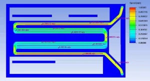
Delta-T Data Differences
Under high heat flux conditions (>100 W/cm²), traditional VCs exhibit noticeable temperature gradient accumulation. The hot spot area experiences a sharp temperature spike because the planar wick cannot supply liquid fast enough.
In contrast, a 3Dvapor chamber effectively suppresses localized overheating. Depending on the specific design and heat sink integration, a 3D VC can reduce the overall ΔT by 20% to 50%. The result is a highly uniform temperature distribution across the entire thermal module.
In practical designs, Delta-T reduction of 20–50% is achievable depending on geometry and load conditions.
Heat Flux Capability
Traditional vapor chamber:
Limited by capillary return capability
Risk of dry-out at high heat flux
3D vapor chamber:
Multiple liquid return paths
Improved capillary support
Higher critical heat flux threshold
Why 2D Vapor Chambers Fail at Extreme Heat Flux
Typical Failure Modes
Dry-out: The working fluid evaporates faster than the capillary action can replenish it.
Vapor Congestion: High vapor velocity chokes the internal cavity, increasing pressure and temperature.
Thermal Bottleneck: Heat cannot move to the condenser fast enough, rendering the external heat sink ineffective.
Root Causes
These failures occur because 2D VCs rely entirely on planar diffusion. The vapor path is simply too long for extreme loads, and the flat capillary structure becomes overloaded by the demand for rapid liquid return.
Manufacturing Challenges of 3D Vapor Chambers
The performance advantages of a 3D vapor chamber come with significant manufacturing complexity.
Vertical Structure Integration
One of the main challenges is ensuring:
Continuous thermal connection between vertical structures and the base
Minimal interface resistance
Poor integration directly reduces performance gains.
Sealing and Reliability
Multi-layer structures increase leak risk
Vacuum integrity is harder to maintain
Long-term reliability requires tighter process control
Wick Structure Uniformity
Consistent distribution of capillary material is critical
Uneven wick leads to localized dry-out
Manufacturing Yield
Constructing these multi-layer thermal systems imposes rigorous demands on sintering processes, diffusion bonding, and CNC machining precision, which directly impacts production yield.
When Should You Upgrade to a 3D Vapor Chamber?
Consider upgrading your thermal architecture if you are encountering the following engineering parameters:
Heat flux exceeds 100–200 W/cm².
Localized hot spots cannot be mitigated by thicker base plates or larger fans.
You are cooling multi-die packages (AI, high-end GPUs, IGBTs) with concentrated heat loads.
Z-height is limited, but power dissipation requirements continue to rise.
If these apply to your project, a traditional VC has likely reached its physical limits.
Design Considerations: 2D vs. 3D VC Selection Guide
Selection Guide
Moderate heat load → standard vapor chamber
High heat flux with spreading requirement → enhanced VC
Extreme localized heat → 3D vapor chamber
The decision should be based on thermal resistance targets and heat distribution, not just total power.
Custom Vapor Chamber and Heat Sink Solutions
In many applications, off-the-shelf solutions are insufficient.
A tailored combination of:
Vapor chamber
3D vapor chamber
Heat sink design
is often required to achieve optimal results.
Custom solutions can include:
Geometry optimization
Internal structure design
Integration with heat sinks or cold plates
Facing Heat Flux Limits? Let’s Evaluate Your Design
If you cannot reduce chip temperatures, your current vapor chamber is failing, or you are unsure if your next-generation hardware requires a 3D vapor chamber, we can provide precise engineering data.
We offer:
Free thermal design for manufacturability (DFM) evaluation.
ΔT and thermal resistance projections.
Objective assessment on whether a 3D vapor chamber is required for your heat sink assembly.
FAQ
What is the difference between a 2D and 3D vapor chamber?
A 2D vapor chamber spreads heat horizontally (X-Y plane) using a flat cavity. A 3D vapor chamber incorporates vertical columns or integrated heat pipes to move heat volumetrically (X-Y-Z planes), drastically reducing the path to the cooling fins.
What is the maximum heat flux for a vapor chamber?
Traditional 2D vapor chambers typically handle up to 50-100 W/cm² before capillary limits cause dry-out. Advanced 3D vapor chambers can be engineered to handle extreme heat fluxes exceeding 300-500 W/cm², depending on the wick structure and fluid.
When to use a 3D vapor chamber?
Use a 3D vapor chamber when cooling AI processors, high-power IGBTs, or dense multi-chip modules where heat flux exceeds 100 W/cm² and traditional 2D spreading results in unacceptable localized hot spots.
Is a 3D VC more expensive?
Yes. Due to the complex manufacturing processes—including diffusion bonding, multi-axis CNC machining, and intricate 3D wick sintering—3D vapor chambers carry a higher unit cost but provide necessary thermal relief for high-value silicon.