Developing High-Efficiency Liquid Cooling Solutions: Design and Testing Methods for Liquid Cooling Plates———Test Methods
TEST METHODS 123456
3 Test Methods
3.1 Mechanical Tests
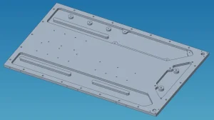
3.1.1 Dimensions
Use the following measurement methods to verify whether the dimensions of the cold plate meet the product requirements of the cold plate:
Measure the height of the cold plate using a vernier caliper.
Measure the length, width, spacing, and height of the flow channels inside the cold plate using a vernier caliper.
Measure the flatness of the bottom surface of the cold plate base according to the ISO 12781-2:2011 standard.
Measure the roughness of the bottom surface of the cold plate base according to the ISO 21920-2:2021 standard.
Use X-ray or other similar imaging techniques to check for deformation, damage, or foreign objects in the fins of the flow channels.
3.1.2 Structure
Refer to the technical specifications of the processor to obtain the key structural requirements and recommended test methods to verify the structural requirements (such as mass, flatness, etc.) of the cold plate thermal solution.
3.1.3 Cold Plate Integration
In order to confirm that the design meets the cold plate assembly requirements, the cold plate needs to complete the following verifications:
Inspect the cold plate using X-ray or other similar analysis methods to detect manufacturing defects on the cold plate heat exchanger, such as voids, foreign objects in the flow channels, welding quality, etc.
Verify that the cold plate heat exchanger and the fixing bracket of the split-type cold plate can be assembled together without interference.
Check the cold plate connector and confirm whether its specifications (such as dimensions, barb configuration, orientation, etc.) meet the product design requirements.
Integrate the cold plate into the product cold plate assembly and conduct a hydrostatic pressure test to confirm that there is no leakage between the fluid exchanger, the connector, and the coolant pipeline.
3.1.4 Appearance
Visually inspect the exterior of the cold plate according to the factory appearance inspection standard and confirm that the requirements of Section 1.2.1.4 are met.
Immerse the cold plate heat exchanger in an ultrasonic cleaning tank or similar functional equipment, rinse it with a transparent liquid, and then check whether the discharged liquid has discoloration and whether the particle size in the rinse liquid is less than 50μm.
3.2 Performance Tests
3.2.1 Thermal Performance
Install the cold plate with the recommended TIM2 material on the processor stack corresponding to the thermal function on the representative product board, and connect the cold plate heat exchanger to the coolant circulation.
Before starting the thermal performance test, ensure that there are no air bubbles in the coolant test loop.
Stabilize the fluid flow rate through the cold plate heat exchanger and apply power to the processor.
Maintain a constant power setting until the case temperature (Tc) and the inlet liquid temperature (TL) are stable.
When stability is achieved, record the pressure drop measured through the cold plate assembly, the case temperature of the processor (Tc), the inlet liquid temperature (TL), the power applied to the processor (Q), and the fluid flow rate through the cold plate heat exchanger.
The thermal resistance of the cold plate at a specific coolant flow rate is calculated by the following formula (1):
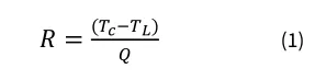
Where:
R — Thermal resistance of the cold plate, in °C/W
Tc — The case temperature of the thermal component during the test, in °C
TL — The fluid temperature at the inlet of the cold plate during the test, in °C
Q — The power applied to the thermal component during the test, in W
R — Thermal resistance of the cold plate, in °C/W
Tc — The case temperature of the thermal component during the test, in °C
TL — The fluid temperature at the inlet of the cold plate during the test, in °C
Q — The power applied to the thermal component during the test, in W
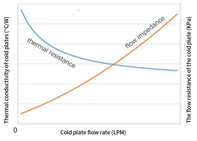
In order to understand the thermal performance of the cold plate design as the coolant flow rate changes, the thermal resistance of the cold plate design should be measured at multiple coolant flow rates. Figure 9 provides an example of the thermal performance curve between the cold plate and the coolant flow rate of the cold plate.
3.2.2 Fluid Pressure Drop of the Cold Plate
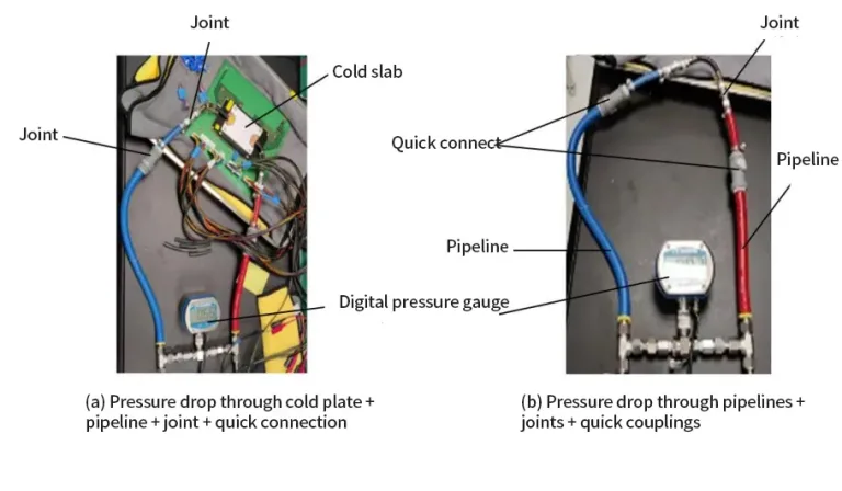
Use Figure 10a as a guide to configure a laboratory bench-top Technology Cooling System (TCS) loop, which includes a cold plate, coolant pipelines, quick disconnect connectors, and a Coolant Distribution Unit (CDU). Connect a digital pressure gauge (such as Omega DPG409-015G) between the coolant inlet and outlet pipelines of the cold plate. Supply liquid to the cold plate from the CDU at a constant flow rate and record the pressure on the pressure gauge.
Disconnect the cold plate from the laboratory bench-top TCS loop according to Experimental Configuration 10a, and directly connect the coolant inlet and outlet pipelines together, as shown in Configuration 10b. Record the pressure on the pressure gauge in Laboratory TCS Configuration 10b at the same CDU flow rate.
The pressure drop of the cold plate is the difference between the pressures recorded in Experimental Setups 10a and 10b at the same CDU flow rate. The influence of the coolant flow rate of the cold plate on the flow resistance of the cold plate is shown in Figure 9.
The pressure drop of the cold plate must be lower than the coolant pressure provided to the cold plate by the Technology Cooling System (TCS) to ensure the forward flow of the coolant. In order to meet the thermal performance requirements, the coolant flow rate target needs to compensate for the expected pressure drop of the cold plate.
3.3 Reliability Tests
3.3.1 Hydrostatic Pressure Test
The hydrostatic pressure test is a key quality and reliability test to detect the presence of leakage under normal and expected operating conditions. There are two industry standards available for defining the hydrostatic pressure test method:
The European standard EN 1779 defines the method of using pressurized gas for leakage detection:
Pressure Decay Test: Measure the reduction in the total pressure of the cold plate. It is recommended that the pressure drop be less than 0.5%.
Immersion Bubble Test: The cold plate is pressurized and immersed in a liquid. Leakage is detected by the formation of bubbles or a stream of bubbles around the cold plate.
The UL Solutions standard IEC FDIS 62368-1 defines the pressurization time and safety factor for the hydrostatic leakage test. These tests can pressurize the cold plate using gas or coolant:
Pressurize the cold plate to the maximum operating pressure and check the cold plate and its connectors for leakage after 5 minutes.
Pressurize the cold plate to three times the maximum operating pressure and check the cold plate and its connectors for leakage after 2 minutes.
3.3.2 Corrosion Test
Fluid Compatibility
The cold plate technology cooling system will be composed of a combination of metals and polymer/elastomer materials in contact with the coolant. The reliability of the cold plate depends on the chemical compatibility between the coolant and all the wetted materials. The coolant needs to provide reliable anti-corrosion protection for the metal components and prevent the release of contaminants from the polymer and elastomer components.
Some polymer/elastomer materials may absorb the preservative compounds in the coolant, thus reducing the concentration of the preservatives in the coolant. The list of wetted materials needs to demonstrate the compatibility of the coolant, and some recommended evaluation methods include:
Use ASTM standard D2570 for the corrosion and material compatibility test of the coolant with metals, evaluate the effect of the circulating coolant on the metal specimens to detect galvanic corrosion under controlled laboratory conditions.
Use ICP (Inductively Coupled Plasma) to measure the concentration of metal ions in the solution according to ASTM standards D6130 and D5185 to identify early signs of corrosion and schedule preventive maintenance.
Conduct pH value and reserve alkalinity tests of the coolant according to ASTM standards D1287 and D1121 to measure the decrease in reserve alkalinity and pH value and identify the deterioration of the coolant due to the degradation of ethylene glycol into glycolic acid.
Use ion chromatography to test the concentration of chloride ions and other anions in the coolant according to ASTM standard D5827 to measure the concentration of active anions that cause pitting corrosion of metals.
Test the coolant using gas chromatography (GC) and liquid chromatography (LC) to track the concentration of organic preservatives and identify other organic contaminants that have entered the coolant.
Salt Spray Test
The salt spray test should be carried out in a salt spray chamber according to ASTM B117 standard to evaluate the corrosion resistance of the external coating of the cold plate. Passivation or anodization of the cold plate surface can reduce the corrosion risk in the salt spray test.
Seal the inlet and outlet of the cold plate and place its sample in a salt spray chamber at a temperature of 35°C.
The mass ratio concentration of the NaCl solution is 5%.
The pH value of the NaCl solution is 6.5-7.2.
The salt spray volume is about 2 ml/hour/80 cm².
The exposure test time is 8 hours.
The thermal performance of the cold plate should be measured after the salt spray test, and there should be no statistically significant thermal degradation. It is also recommended to conduct a hydrostatic pressure test on the cold plate after the salt spray test is completed to detect any leakage caused by the material degradation due to the corrosion test.
3.3.3 Dynamic Characteristics
Impact
Install the cold plate on the corresponding product CPU stack on the representative product board and perform an impact test that meets the product certification requirements. Conduct a visual inspection to confirm that the cold plate still meets the appearance requirements after the impact stress and that the CPU stack or the representative product board is not damaged. Conduct a hydrostatic pressure test on the installed cold plate to verify that the impact stress has not caused leakage in the cold plate and its connectors.
Vibration
Install the cold plate on the corresponding product CPU stack on the representative product board and perform a vibration test that meets the product certification requirements. Conduct a visual inspection to confirm that the cold plate still meets the appearance requirements after the vibration stress and that the CPU stack or the representative product board is not damaged. Conduct a hydrostatic pressure test on the installed cold plate to verify that the vibration stress has not caused leakage in the cold plate and its connectors.
3.3.4 Temperature Cycling
Install the cold plate with the recommended TIM2 material on the processor stack corresponding to the thermal function on the representative product board and perform a temperature or power cycling test plan that meets the product certification requirements. The temperature range should cover all the extreme conditions of the cold plate operating temperature, and the number of cycles should be set according to the estimated number of processor power cycles during the service life of the processor.
The thermal performance of the cold plate after completing the temperature or power cycling test plan needs to meet the product certification requirements. Conduct a hydrostatic pressure test on the installed cold plate to verify that the temperature cycling stress has not caused leakage in the cold plate or its connectors.