Developing High-Efficiency Liquid Cooling Solutions: Design and Testing Methods for Liquid Cooling Plates——Development Requirements
2.1 Mechanical Requirements
2.1.1 Cold Plate Mechanical Design
In addition to the cold plate requirements defined by the processor vendor, the cold plate also needs to meet the following mechanical design requirements:
The cold plate design should comply with the product design requirements, adhere to the product’s Keep Out Zone (KOZ) requirements, and incorporate the Interface Control Diagram (ICD) requirements of the fixing hardware.
The mechanical load exerted on the processor by the cold plate fixing hardware should comply with the package loading requirements defined in the processor specifications and requirements, and remain compliant throughout the entire service life of the cold plate.
The installation and removal of the cold plate should comply with the design and manufacturing specifications of the processor.
The flatness of the bottom surface of the cold plate may affect its mechanical and thermal performance, and should be specified in accordance with the cold plate performance requirements.
The average roughness (Ra) of the bottom surface of the cold plate should be specified according to the cold plate mechanical and thermal performance requirements.
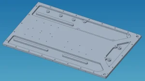
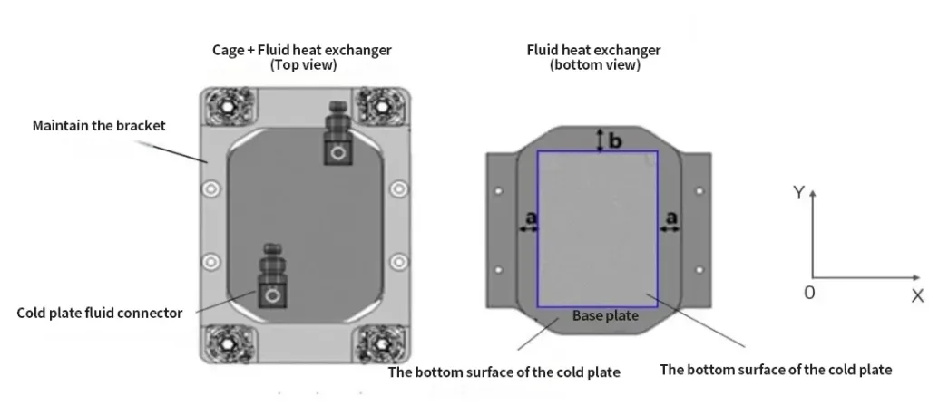
The dimensions of the bottom surface of the cold plate that come into contact with the processor’s Integrated Heat Spreader (IHS) or die area in the X and Y directions may affect the thermal performance, and should be designed according to the cold plate performance requirements. The blue outline in Figure 6 represents the IHS or die area of the processor.
2.1.2 Cold Plate Fluid Connectors
The cold plate fluid connectors need to meet the following requirements:
During the hydrostatic pressure test, there should be no leakage or deformation between the cold plate connector and the cold plate heat exchanger interface.
During the hydrostatic pressure test, there should be no leakage or deformation between the cold plate connector and the coolant pipeline.
The design should prevent fluid stagnation or cavitation phenomena.
2.1.3 Integration of Cold Plate Cooling Circuit
In order to integrate the cold plate into the cooling circuit, the following requirements need to be considered:
The position and orientation of the cold plate connectors should take into account the routing of the product coolant pipelines.
The difference in electrode potential of the wetted metals in the technology cooling system should be as small as possible to prevent corrosion of the cold plate. If the list of wetted materials contains different metals, it is highly recommended to implement a comprehensive corrosion certification program to evaluate the corrosion potential of different metals in the coolant.
The electrochemical potential difference at any metal-to-metal interface in the cold plate design should not exceed 0.15V to prevent galvanic corrosion.
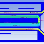
The fin thickness, fin height, and fin pitch in the design of the microchannel cold plate heat exchanger will affect the fluid flow rate capacity and the flow resistance of the entire cold plate assembly. The flow resistance of the entire cold plate assembly needs to be lower than the fluid pressure provided by the coolant pump.
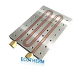
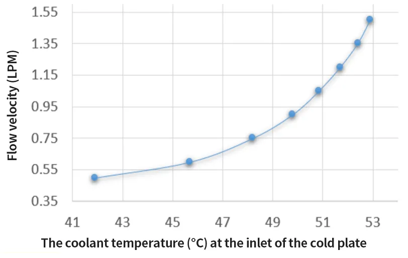
It is recommended to understand the change of the coolant flow rate with temperature (as shown in Figure 8) to evaluate whether it is necessary to adjust the cold plate fluid flow rate according to seasonal temperature changes.
2.1.4 Appearance Requirements of the Cold Plate
The cold plate should meet the following appearance requirements:
The top cover of the cold plate should be smooth, free of visible defects and deformations.
The bottom surface of the cold plate base should be free of visible defects and deformations.
The fixing bracket of the cold plate should be free of visible defects and deformations.
The fluid connector of the cold plate should be free of visible defects and deformations.
The performance of the cold plate needs to meet the processor temperature requirements specified in the thermal specifications provided by the processor vendor to ensure the performance of the product throughout its service life.
In order to determine the performance requirements of the cold plate, the following thermal boundary conditions need to be defined:
The processor temperature that should not be exceeded according to the processor thermal specifications.
The coolant temperature and flow rate provided to the processor by the cold plate technology cooling system.
The maximum coolant flow rate entering the cold plate should be lower than 1.5 m/s to prevent erosion of the cold plate components.
2.3 Reliability Requirements
2.3.1 Hydrostatic Pressure
The cold plate needs to be subjected to a hydrostatic pressure test in accordance with the IEC FDIS 62368-1 standard, and there should be no detectable leakage or mechanical deformation. The dimensions of the cold plate before and after the hydrostatic pressure test should be statistically equivalent.
2.3.2 Corrosion and Fluid Compatibility
The wetted surface of the cold plate needs to be chemically compatible with the coolant and resistant to corrosion. The concentrations of bactericides and preservatives in the coolant need to be maintained at the minimum concentration to provide biological and corrosion protection for the cold plate when tested together with the complete list of wetted materials in the cooling circuit.
Salt Spray Test
The cold plate needs to complete a salt spray test according to the ASTM B117 standard to evaluate the corrosion resistance of the external surface of the cold plate. After the salt spray test is completed, there should be no corrosion, pitting, or discoloration observed on the surface of the cold plate. It is recommended to conduct a hydrostatic pressure test on the cold plate assembly after the salt spray test to detect leakage caused by the degradation of the cold plate material.
2.3.3 Dynamic Characteristics
Impact
The cold plate needs to complete an impact test that complies with the product certification standard, and conduct a hydrostatic pressure test after the impact stress to detect leakage. The thermal performance of the cold plate after the impact test should be statistically equivalent.
Vibration
The cold plate needs to complete a vibration test that complies with the product certification standard, and conduct a hydrostatic pressure test after the vibration stress to detect leakage. The thermal performance of the cold plate after the vibration test should be statistically equivalent.
2.3.4 Temperature Cycling
It is recommended that the cold plate complete a temperature cycling test plan and then conduct a hydrostatic pressure test to detect leakage caused by the interaction between extreme transportation or operating temperature conditions and the manufacturing process.