Research Progress of Thermal Management System for Solar Cells Based on Heat Pipe Technology
1.The temperature effect and thermal management of solar cells
2. Common thermal management technologies for solar cells
-2.1 Traditional Cooling Technology (Air Cooling technology)
-2.2 New Cooling Technology (Microchannel Cooling Technology)
3 Thermal management of solar cells based on heat pipe technology
4 Conclusion
Abstract
Summary of Thermal Management Systems for Solar Cells and Insights for Emerging Cooling Technologies
This paper provides a comprehensive summary of research on thermal management systems (TMS) for solar cells, offering actionable recommendations for the development of novel cooling technologies. The goal is to guide advancements in solar cell thermal management, addressing critical challenges in energy efficiency and sustainability.
Environmental Context and Renewable Energy Imperative
The rapid development and utilization of new technologies have accelerated the overexploitation of natural resources, exacerbating environmental issues such as the greenhouse effect and ozone layer depletion. These challenges not only threaten the living conditions of future generations but also severely constrain industrial innovation due to the drastic decline in available resources. Solar energy, with its advantages of being clean, abundant, and universally applicable, has emerged as a cornerstone of renewable energy technology development, encompassing both photovoltaic (PV) and solar thermal applications.
Photovoltaic Power Generation Technology
Photovoltaic (PV) technology directly converts solar energy into usable electricity, offering a sustainable solution to global energy demands. As solar cells evolve toward higher efficiency and power density, effective thermal management has become critical to mitigate performance degradation caused by overheating under high irradiance and current conditions.
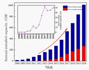
Figure 1: Global Photovoltaic (PV) Installed Capacity Trends & Forecast
The chart illustrates a remarkable growth trajectory, with global PV capacity surging from 15.7 GW in 2008 to 506 GW in 2018. This exponential increase is primarily driven by declining installation costs and robust policy incentives worldwide. An inset highlights China’s pivotal role, where annual installations reflect the nation’s dominance in the sector. With a cumulative capacity of 219.5 GW—comprising approximately one-third of the global total—China continues to lead the charge in renewable energy adoption.
1.The temperature effect and thermal management of solar cells
Currently, the laboratory conversion efficiency of concentrating solar cells has reached as high as 47.1%, while the conversion efficiency of popular monocrystalline silicon cells in the market is only 26.7%. Factors such as component type, electrical losses, and operating environment have consistently constrained the improvement of photovoltaic power generation system efficiency (Figure 2). Among these, the temperature effect is a key factor affecting photovoltaic cell performance: the system’s output power and energy conversion efficiency significantly decrease as the operating temperature of photovoltaic cells rises. Studies show that for every 1°C increase in the operating temperature of solar cells, the conversion efficiency decreases by 0.4% to 0.5%. Although the temperature effects vary across different types of solar cells, they may still hinder the efficiency improvements brought by advancements in solar cell technology and materials.
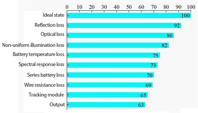
Figure 2 shows the proportion of performance losses caused by various factors in photovoltaic systems
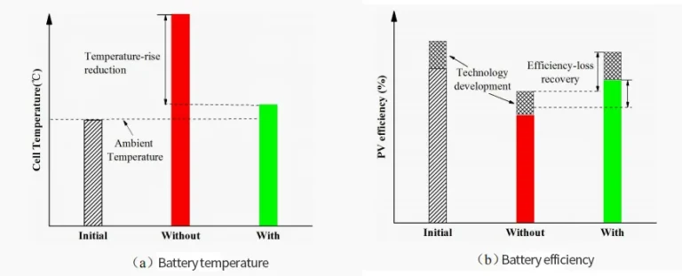
As shown in Figure 3(a), solar cells without light irradiation exhibit high conversion efficiency and operate normally at ambient temperature. Conversely, under irradiance, most of the absorbed radiant energy converts to heat, causing a significant temperature rise in the cells. Typically, when the cell temperature reaches 70°C, its electrical performance is severely impacted. For a solar cell with a temperature coefficient of -0.5%/°C, the relative reduction in conversion efficiency can be as high as 20–25%.
2.Common thermal management technologies for solar cells
Research on solar cell cooling has been conducted to address issues such as temperature non-uniformity, local overheating, and rising average temperatures caused by increased concentration ratios, light intensity non-uniformity, and high heat flux density. As 散热技术 (heat dissipation technologies) and demands evolve, thermal management techniques for solar cells are categorized into traditional cooling methods (air cooling, liquid cooling) and novel cooling technologies such as microchannel cooling, jet impingement cooling, and phase-change material (PCM) cooling. This paper introduces and summarizes the applications of both traditional and novel cooling technologies in concentrating solar cells.
2.1Traditional Cooling Technologies
Air Cooling
Air cooling reduces solar cell operating temperature through natural or forced convection, where air flows over heat dissipation modules. For example, Cuce et al. installed aluminum fin heat sinks on the back of solar cells, increasing output power by 13%. Soliman et al. tested similar methods, achieving temperature reductions of 5.4% (natural convection) and 11% (forced convection), with output power increases of 8% and 16%, respectively. Bayrak et al. confirmed through outdoor measurements that fin cooling keeps cells within safe temperature ranges.
Liquid Cooling
Liquid cooling transfers heat generated by solar cells to the environment via liquid working fluids. Zilli et al. used a water-cooled spray system under high irradiance, achieving relative increases of 12.26% in power and 12.17% in efficiency for polycrystalline silicon cells. Schiro et al. developed and experimentally validated a mathematical model for water-cooled battery backplanes.
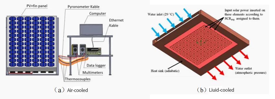
Table 1 Summary of Research Achievements on Traditional Cooling Technologies Based on Solar Cell Cooling
| Battery Type | Cooling Method | Test Environment | Efficiency | Temperature |
|---|---|---|---|---|
| pc – Si | Fin Heat Sink | G=200−800W/m2, Ta=25∘C | ↑13%(P) | ↓17.5∘C |
| \multirow{2}{*}{PV cell} | Fin | \multirow{2}{*}{G=500W/m2, Ta=25∘C} | ↑8%(P) | ↓5.4% |
| Fin + Heat Sink | ↑16%(P) | ↓11% | ||
| Pc – Si | Fin | Outdoor measurement (Elazig, Turkey) | 11.55% | 45.42∘C |
| PV module | Air – conditioning System Exhaust Air | G=1000W/m2, Ta=25∘C | ↑7.2%(η) | ↓ |
| pc – Si | Air Duct + TMS | G=1000W/m2, Ta=25∘C | ↑4%(η) | ↓4∘C |
| pc – Si | Air Duct + FIN | G=1000W/m2, Ta=25∘C | ↑10%(η) | ↓10∘C |
| pc – Si | EAHE + Air Channel | G=1000W/m2, Ta=25∘C | ↑18.9%(P) | 42∘C |
| pc – Si | Water – cooled Sprinkler System | Outdoor measurement (Paraná, Brazil) | ↑12.26%(P) | 35∘C |
| \multirow{3}{*}{m – Si} | Front + Water Spray Cooling | \multirow{3}{*}{G=810−850W/m2, Ta=27−30∘C} | ↑2.5%(η) | 29.6∘C |
| Rear + Water Spray Cooling | ↑3.6%(η) | 33.7∘C | ||
| Front & Rear + Water Spray Cooling | ↑5.9%(η) | 24.1∘C | ||
| TJ cell | Straight Fins + Water (Active Cooling) | Ta=25∘C, CR=500X, V=0.01m/s | ↑39.5% | 60∘C |
| TJ cell | Liquid Immersion + Dimethyl Silicone Oil | G=1000W/m2, Ta=25∘C, CR=500X | ↑40.572% | – |
Table 1 lists the research achievements of applying traditional cooling technologies to solar cells. From the above research results of applying traditional cooling technologies to solar cells, it can be found that traditional cooling technologies (air cooling, liquid cooling) have the characteristics of simple structure and low cost, but they are greatly affected by the ambient temperature and have limited cooling effects. As the concentration ratio is further increased, the contradiction between the cost caused by additional power consumption (pumps, fans) and the improvement of cell performance needs to be further optimized and solved.
2.2 New cooling technology
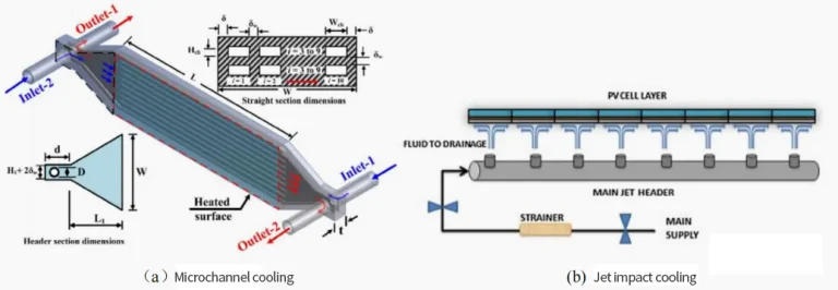
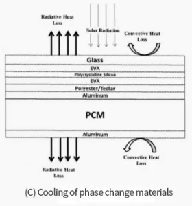
Table 2 summarizes the research achievements of applying new – type cooling technologies to solar cells. From the above research achievements of new – type cooling technologies applied in the field of solar cell heat dissipation, it can be seen that new – type cooling technologies have significantly improved in heat transfer capacity, temperature uniformity, and from multiple perspectives compared with traditional cooling technologies, and have more far – reaching development prospects in the heat dissipation application of concentrating solar cells.
| Battery Type | Cooling Method | Test Conditions | Efficiency | Temperature |
|---|---|---|---|---|
| m – Si | Microchannel + Water | G=1000W/m2, Ta=22∘C | ↑30.75%(P) | 46.73∘C |
| TJ cell | Microchannel + Water | G=850W/m2, Ta=20∘C | 35%(ηth) | 49.8∘C |
| Si | Microchannel + Heat Sink | Ta=25∘C, CR=2X | ↑8%(η) | 43.23∘C |
| TJ cell | Foam Material + Water | G=1000W/m2 | ↑1.5%(η) | N/A |
| Si | PCM | Ta=25∘C, V=4m/s | ↑5%(η) | ↓6∘C |
| pc – Si | Aluminum Channel + /PCM + Water | G=632.5−650.8W/m2, Ta=35.4−37.2∘C | ↑40.5%(P) | ↓14.5∘C |
| PV cell | Jet Impingement + Water | G=1000W/m2, Ta=25∘C | ↑82.6%(η) | 31.1∘C |
| TJ cell | Jet Impingement + Water | G=1000W/m2, Ta=25∘C, CR=50X | 39.57%(η) | 65∘C |
Table 2 presents a summary of the research results of the new cooling technology based on solar cell cooling
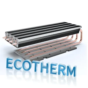
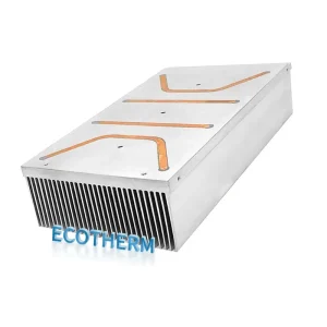
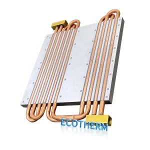
3 Thermal management of solar cells based on heat pipe technology
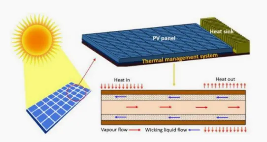
In the cooling application of solar cells, compared with traditional cooling technologies and new – type cooling technologies (such as microchannels, jet impingement, phase – change materials, etc.), it can be seen from Table 3 that heat pipe cooling can effectively reduce the operating temperature of the cells. Without the need to avoid additional power consumption (such as pumps, fans, etc.), as a two – phase passive heat exchange device, the heat pipe cooling technology has strong heat transfer capacity. The long – distance heat transfer capacity of loop heat pipes can further promote the development of the PV/T system.
| Battery Type | Cooling Method | Test Conditions | Efficiency | Temperature |
|---|---|---|---|---|
| N/A | Flat – plate Pulsating Heat Pipe | Ta=18∘C, V=1.5m/s, β=16%−50% | 0.05K/W(R) | 6∘C(ΔT) |
| N/A | Pulsating Heat Pipe | G=830W/m2, Ta=30∘C, V=3.2m/s | 17.4(V) | 64∘C |
| m – Si | Pulsating Heat Pipe | G=1000W/m2, Ta=18∘C, β=40% | ↑18%(η) | 16.1K(ΔT) |
| m – Si | Finned Heat Pipe | G=500W/m2, Ta=35∘C | 1.878V(U) | ↓13.8K |
| TJ cell | Finned Heat Pipe | G=485W/m2, Ta=30∘C, β=30% | 34.55% | 63∘C |
| TJ cell | Micro Heat Pipe Array | G=900±5W/m2, Ta=40.4±2∘C, V=0.22±0.03m/s | ↑22.4%(P) | ↓8∘C |
| c – Si | Microchannel Heat Pipe | Outdoor test (Hefei, China) | 7.6%(η) | 3∘C(ΔT) |
| a – Si | Nano – coated Heat Pipe Plate | G=1100W/m2, Ta=25∘C, V=0−1m/s | N/A | ↓22∘C |
| a – Si | Nano – coated Heat Pipe Plate | G=1000W/m2, Ta=20∘C | ↑56%(η) | 11∘C |
| PV Plate | Heat Pipe Plate | G=400−1000W/m2, Ta=10−30∘C | ↑15%(η) | 28−33∘C |
4 Conclusion