Custom Heat Sink Design for Solar Inverter Cooling and IGBT Thermal Management
Solar inverters can overheat during long periods of operation, which can reduce performance and shorten system life. This article explains how custom heat sink design supports solar inverter cooling and helps manage IGBT temperature more effectively. With the right thermal solution, inverter systems can operate more safely, efficiently, and reliably.
Solar Inverter Cooling Basics
Solar inverter cooling begins with one simple rule: remove heat from the IGBT, MOSFET, and diode quickly enough to keep junction temperature below its limit. In inverter power module thermal management, that matters because switching and conduction losses turn into heat every time the inverter operates. Industry tests and design guides show that even a small increase in thermal resistance can move the device into a hotter operating range, which shortens service life and increases the risk of failure. Ecothermgroup often treats this as the foundation of custom heat sink design: first control heat flux, then improve the thermal path from the module case to the heat sink.
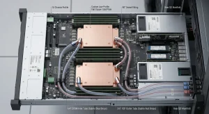
Main heat sources in solar inverter cooling are usually the power module, nearby inductors, and other high-load parts inside the enclosure. In many solar inverters, IGBT cooling is the most critical point because these switching devices create both steady heat and rapid temperature rise during load changes. For that reason, a custom aluminum heat sink, air-cooled heat sink, or liquid cold plate is selected based on power level, enclosure space, and ambient conditions. In higher-density systems, thermal simulation and CFD thermal analysis are commonly used to identify hot spot reduction needs before tooling begins.
| Heat Source | Cooling Concern | Typical Design Response |
|---|---|---|
| IGBT / IGBT heat sink area | High junction temperature and switching device heat dissipation | Low thermal resistance base, strong clamping, quality thermal interface material |
| SiC MOSFETs | Fast heat spikes and local hot spots | Better contact pressure and CFD thermal analysis |
| Diodes and nearby parts | Semiconductor device cooling and shared heat spread | Larger fin area or bonded fin heat sink |
| Whole power stage | Inverter power module thermal management | Forced convection heat sink or liquid cold plate |
Cooling goals are practical and measurable: lower thermal resistance, keep junction temperature stable, and reduce temperature swings over long daily cycles. That is why many engineers compare extruded heat sink, skived fin heat sink, zipper fin heat sink, CNC machined heat sink, and heat pipe heat sink options before choosing one. Natural convection heat sink designs can work in smaller, lower-power units, but forced convection is more common when heat flux is high. Surface treatment also matters; an anodized aluminum heat sink can improve corrosion resistance and help with radiation in harsh outdoor use.
- Check module flatness and mounting pressure before assembly.
- Use the right thermal interface material to fill microscopic air gaps.
- Match fin geometry to airflow direction and enclosure limits.
- Review service temperature, not only rated power.
In practice, the best solar inverter cooling solution is not simply a larger heat sink. It is a balanced path from device to base plate to fins or liquid channel, with careful control of contact quality, airflow, and thermal simulation results. For higher-power systems, a liquid cold plate may be the safer choice; for lower-cost units, a well-designed forced convection heat sink can be enough if the mounting, surface treatment, and thermal resistance are controlled well. This is the starting point for reliable solar inverter cooling.
IGBT Thermal Challenges
In solar inverter cooling, the IGBT is one of the main heat sources because both conduction losses and switching losses convert electrical energy into heat. In inverter power module thermal management, this heat must travel through the chip, package, thermal interface material, and IGBT heat sink quickly enough to keep the junction temperature under control. Ecothermgroup often designs a custom aluminum heat sink for this thermal path because a generic part may not match the actual heat flux, mounting pressure, or enclosure airflow of the inverter.
Junction Temperature Control
The main goal in IGBT cooling is to keep the junction temperature below the device limit during daily load changes. Thermal simulation and CFD thermal analysis are widely used to estimate temperature rise before hardware testing. A low thermal resistance path, flat contact surfaces, and a stable thermal interface material can reduce hot spot problems caused by uneven contact or poor heat spreading. In many solar inverter designs, an air-cooled heat sink is enough for moderate power, while a liquid cold plate or heat pipe heat sink is selected when the power module runs hotter or cabinet space is limited.
| Challenge | Typical Design Response |
|---|---|
| High junction temperature | Lower thermal resistance with a larger fin area or liquid cold plate |
| Uneven heat spread | Use skived fin heat sink, bonded fin heat sink, or zipper fin heat sink for better surface area |
| Poor contact pressure | Improve flatness, torque control, and thermal interface material selection |
Reliability and Life
Thermal cycling is a major life-limiting factor for IGBTs, because repeated junction temperature changes can stress solder joints, wire bonds, and the package structure. Industry guidance commonly recommends keeping the temperature rise as low and stable as possible, since long-term reliability depends more on steady operation than on short peak runs. For this reason, solar inverter cooling projects often use custom heat sink design rather than standard extruded heat sink parts when the load profile changes often.
Manufacturing experience also matters. A CNC machined heat sink may be helpful where mounting accuracy is strict, while an anodized aluminum heat sink can improve surface finish quality and corrosion resistance in outdoor solar sites. For high-volume inverter power module thermal management, extruded heat sink designs are often cost-effective, but they may need careful fin geometry tuning to handle MOSFET cooling, diode thermal management, and IGBT heat sink needs together.
Losses and Hot Spots
IGBT loss distribution is rarely uniform, so one small area can become a hot spot even when the average temperature looks safe. This is why switching device heat dissipation should be checked at the real operating point, not only at nameplate power. Double-sided cooling concepts can lower the maximum junction temperature and reduce thermal resistance, but most solar inverters still rely on strong single-sided IGBT cooling with good airflow or a liquid cold plate when heat density is high.
- Check the worst-case load, not only normal operation.
- Match fin type to airflow: natural convection heat sink for passive systems, forced convection heat sink for fan-cooled units.
- Verify mounting torque and surface flatness before final assembly.
For safety, the final design should always be validated by thermal testing, because real cabinet airflow, dust, and aging can change performance over time. Solar inverter cooling works best when custom heat sink geometry, interface quality, and simulation results are developed together.
Custom Heat Sink Design
In solar inverter cooling, custom heat sink design begins with the IGBT module’s actual power loss, not a generic sizing rule. Industry practice is to keep junction temperature below the device limit because every extra degree can speed up aging and reduce service life. Ecothermgroup often designs around the full thermal path: semiconductor case, thermal interface material, heat sink body, and ambient air. This is also why power module cooling for inverters often uses thermal simulation and CFD thermal analysis before tooling is made.
| Design Choice | Best Use in Solar Inverter Cooling | Main Thermal Benefit |
|---|---|---|
| Extruded heat sink | Cost-sensitive air-cooled heat sink designs | Good balance of cost and thermal resistance |
| Skived fin heat sink | High heat flux IGBT cooling in limited space | High fin density and better heat dissipation |
| Bonded fin or zipper fin heat sink | Large inverter power module thermal management | Flexible geometry and stronger surface area |
| Liquid cold plate | Very high load or compact enclosure | Lower temperature rise and better hot spot reduction |
Material Selection
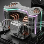
For most custom heat sink projects, a custom aluminum heat sink is preferred because aluminum offers good conductivity, low weight, and easy machining. It also supports CNC machined heat sink features when flatness and mounting accuracy matter for IGBT heat sink contact quality. In more demanding designs, a heat pipe heat sink or liquid cold plate may be added when switching device heat dissipation is too high for air alone. A practical approach is simple: choose the material and base thickness to match thermal resistance targets, enclosure space, and airflow.
Real inverter designs often combine IGBT cooling, MOSFET cooling, and diode thermal management in one assembly, so material selection must handle different heat sources without creating a large junction temperature gap between devices.
Fin Geometry
Fin geometry has a direct effect on temperature rise and heat flux control. Natural convection heat sink layouts usually need wider fin spacing, while forced convection heat sink designs can use tighter channels to increase surface area. The right fin height, thickness, and pitch depend on fan speed, dust level, and available pressure drop. For solar inverter cooling, CFD thermal analysis is useful because it shows whether air actually reaches the hot spot near the semiconductor device cooling zone.
- Use wider fin spacing for natural convection and low-noise systems.
- Use denser fins for forced airflow and compact inverters.
- Check enclosure clearance before selecting skived, bonded, or zipper fin options.
A practical rule is to treat fin design as a system decision, not only a heat sink decision. If the airflow path is poor, even a large IGBT cooling plate may not lower thermal resistance enough.
Surface Treatment
Surface treatment helps the heat sink release heat more effectively and also improves durability in harsh outdoor inverter conditions. Anodized aluminum heat sink surfaces are common because they improve corrosion resistance and can support stable operation in humid or dusty sites. A good thermal interface material is equally important, since poor contact can cancel the benefit of a well-designed fin set. In real projects, careful flatness, mounting pressure, and coating choice often matter as much as the base geometry.
For reliable inverter power module thermal management, Ecothermgroup recommends validating the complete design with thermal simulation, then checking temperature near the IGBT module during prototype testing. This is the safest way to confirm hot spot reduction and avoid overconfidence in theoretical values.
Advanced Cooling Structures
In solar inverter cooling, advanced structures are used to keep IGBT heat sink performance stable when power density is high and junction temperature must stay within safe limits. Ecothermgroup often designs custom aluminum heat sink solutions around inverter power module thermal management needs, because IGBT cooling, MOSFET cooling, and diode thermal management all depend on how quickly heat moves away from the switching device. In practice, lower thermal resistance and better heat spreading can reduce hot spot problems and limit temperature rise during long load cycles.
Double-Sided Cooling
Double-sided cooling is often used for power module cooling when a single air-cooled heat sink cannot control heat flux well enough. By removing heat from both the top and bottom of the module, the design can lower maximum junction temperature and improve temperature uniformity across the package. This matters because uneven cooling can increase thermal stress, which is a common reliability concern in solar inverter cooling systems.
Compared with a standard extruded heat sink or CNC machined heat sink, a double-sided layout can distribute the thermal load more effectively, especially for compact inverter assemblies. Thermal simulation and CFD thermal analysis are usually needed to refine fin spacing, surface treatment, and thermal interface material selection before production. In many cases, this approach works best when the module is compact and the airflow path is well controlled.
| Structure | Main Benefit | Typical Use |
|---|---|---|
| Skived fin heat sink | High surface area | Forced convection heat sink layouts |
| Bonded fin heat sink | Flexible fin height | Large custom aluminum heat sink builds |
| Double-sided cooling | Lower thermal resistance | High-power inverter power module thermal management |
Liquid Cold Plates
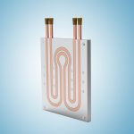
Liquid cold plates are often chosen when air-cooled heat sink designs cannot keep junction temperature low enough in a high-power solar inverter. They remove heat through internal channels, which helps manage switching device heat dissipation in tighter spaces and supports tighter temperature control for IGBT heat sink applications. For this reason, many engineers move from a natural convection heat sink to a forced convection heat sink, and then to a liquid cold plate as power density rises.
In advanced designs, a heat pipe heat sink or liquid cold plate may be paired with an anodized aluminum heat sink base to improve spreading before heat enters the coolant path. Designers usually compare thermal resistance, pump power, sealing risk, and maintenance cost. Industry guidance also shows that liquid systems should be validated carefully, because a small flow issue can create local hot spots. Safety checks, leak testing, and clean coolant channels are essential.
When to Use Each
The right choice depends on load, space, and reliability targets. Air-cooled structures are still common for many solar inverter cooling projects, but liquid cooling becomes more attractive for dense cabinet designs, higher ambient temperatures, or long service-life targets. Ecothermgroup typically recommends CFD thermal analysis early in the design stage so the structure matches the real heat flux and airflow or coolant conditions.
- Use double-sided cooling when the module needs better temperature uniformity and a lower peak junction temperature.
- Use liquid cold plates when compact size and high power density make air cooling insufficient.
- Use advanced fin structures such as zipper fin heat sink or skived fin heat sink when airflow is available and manufacturability matters.
- Use thermal simulation to confirm the design before tooling and production.
For most solar inverter cooling projects, the best result comes from balancing thermal resistance, cost, and serviceability rather than focusing only on the lowest temperature. That balance is what makes advanced cooling structures effective in real inverter power module thermal management.
Design Integration and Validation
In solar inverter cooling, a custom heat sink should be designed as part of the full thermal path, not as a separate component. Ecothermgroup typically treats the IGBT heat sink, thermal interface material, mounting pressure, and airflow channel as one system, because IGBT cooling and inverter power module thermal management depend on how heat moves from the semiconductor junction to the air or liquid path. In many inverter designs, the main objective is to keep junction temperature stable under switching device heat dissipation, since repeated temperature cycling can shorten service life.
Enclosure Fit
Enclosure fit starts with space, airflow, and service access. A custom aluminum heat sink may be a strong choice for an extruded heat sink or skived fin heat sink design when the enclosure supports direct airflow, while a liquid cold plate or heat pipe heat sink may fit better in dense power module cooling layouts with limited height. For solar inverter cooling, the enclosure must also allow enough clearance for fans, busbars, cable bends, and safe creepage distances around the semiconductor device cooling zone.
Design teams often compare options based on heat transfer needs and packaging limits. The table below shows common fit trade-offs used during inverter power module thermal management.
| Design option | Best fit condition |
|---|---|
| Extruded heat sink | Moderate heat load and simple enclosure space |
| Skived fin heat sink | High surface area in a compact footprint |
| Liquid cold plate | Very high power density and tight temperature rise control |
| Bonded fin heat sink | Large dissipating area with flexible geometry |
Manufacturing Tolerances
Manufacturing control affects thermal resistance almost as much as fin geometry. Flatness, base thickness, fin spacing, and surface treatment all influence contact quality and heat flux spreading. A CNC machined heat sink can offer tight control for MOSFET cooling and diode thermal management, while a zipper fin heat sink or bonded fin heat sink may be chosen for larger assemblies where shape flexibility matters more than a single-piece body. Anodized aluminum heat sink surfaces are also common because they improve corrosion resistance and support consistent production quality.
Industry practice is to verify tolerance stack-up before tooling is released. Important checks include:
- Base flatness and mounting hole position
- Fin height and fin pitch consistency
- Thermal interface material thickness and squeeze-out
- Clamp force at the power module interface
Testing and Optimization
Validation usually begins with thermal simulation and CFD thermal analysis, then moves to hardware testing under worst-case ambient temperature, load, and transient cycling. This matters because a junction temperature model can look safe in steady state but still miss peak hot spot reduction needs during fast power changes. Measured data should confirm thermal resistance, temperature rise, and airflow behavior in the real enclosure.
For best results, engineers compare predicted and measured values across several operating points. A common validation sequence is shown below.
- Build a thermal model for the inverter power module
- Test the prototype with representative load profiles
- Check junction temperature and case temperature mapping
- Adjust fin geometry, fan speed, or thermal interface material
- Repeat until the target temperature rise is met
Reliable solar inverter cooling is not only about lowering peak temperature; it is about maintaining stable performance over time. In practice, the best custom heat sink design balances IGBT cooling, manufacturability, cost, and enclosure limits without overbuilding the system.
People Also Ask
Why is custom heat sink design important for solar inverter cooling?
Custom heat sinks help draw heat away from high-power components such as IGBTs, SiC MOSFETs, inductors, and control electronics that create a significant thermal load inside solar inverters. A tailored design improves temperature control, boosts efficiency, and helps extend service life.
How do IGBT junction temperature fluctuations affect inverter reliability?
Repeated junction temperature swings create thermal stress in the IGBT module, which is one of the main causes of long-term wear and failure. Keeping temperature variation under control helps improve reliability and extend the operating life of the inverter.
What are the benefits of double-sided cooling in advanced inverter thermal management?
Double-sided cooling reduces thermal resistance by removing heat from both sides of the device, which lowers the maximum junction temperature. This approach is especially useful for high-power designs that need stronger thermal performance in a compact footprint.
What should be considered when integrating a heat sink into a solar inverter enclosure?
The heat sink must fit the enclosure layout while still supporting effective airflow, mounting, and electrical isolation where needed. Material choice, fin geometry, machining tolerances, and surface finish all affect how well the design performs in the final system.
What type of heat sink is best for solar inverter cooling?
The best heat sink depends on the inverter’s power level, available space, cooling method, and cost target. Extruded, bonded-fin, skived, or liquid-cooled designs may be selected based on how much heat must be removed and how tightly the system is packaged.
How do you know if a solar inverter is overheating?
Common signs include reduced output, thermal derating, frequent shutdowns, changes in fan noise, or visible discoloration around hot components. In well-designed systems, temperature sensors and thermal protection features help detect overheating before damage occurs.
Can liquid cold plates improve solar inverter cooling compared with air-cooled heat sinks?
Yes, liquid cold plates can remove more heat than air cooling when thermal loads are high or space is limited. They are often used in demanding inverter designs where stable IGBT temperatures and compact packaging are important.
How is a custom heat sink validated for IGBT thermal management?
Validation usually includes thermal simulation, prototype testing, and temperature measurements under realistic load conditions. The goal is to confirm that junction temperatures, thermal resistance, and heat transfer performance meet reliability targets.