How Fin Spacing and Fin Efficiency Affect Heat Sink Performance
Fin spacing and fin efficiency determine how much of a heat sink’s surface can actually transfer heat to the surrounding air. More fins can add surface area, but spacing them too closely can restrict airflow, increase pressure drop, and reduce the benefit of that added area. This guide explains how spacing, geometry, material, and airflow work together so you can make a more practical first-pass heat sink selection.
Key Takeaways
- Fin efficiency measures how effectively a fin conducts heat from its base and uses its surface area.
- Fin spacing controls airflow access, boundary-layer interaction, and pressure drop; it is related to system performance but is not the same as fin efficiency.
- Natural-convection and forced-air heat sinks usually need different spacing strategies.
- Taller or more numerous fins do not automatically improve cooling. The added area must remain thermally active and accessible to airflow.
- The final geometry should be checked together with the fan, enclosure, mounting interface, and manufacturing method.
In This Guide
1. What Fin Efficiency Means
A heat sink fin is hottest where it joins the base and becomes cooler toward its tip. Because the entire fin is not at the base temperature, its full geometric area cannot be treated as equally effective. Fin efficiency (ηf) is the ratio of the fin’s actual heat transfer to the heat it would transfer if the whole fin were at the base temperature.
For a straight fin of uniform cross-section, a common first-pass expression is:
m = √(hP / kAc)
Here, h is the air-side heat-transfer coefficient, P is the fin perimeter exposed to air, k is the fin material’s thermal conductivity, Ac is the fin cross-sectional area, and Lc is the corrected fin length. The expression is an engineering approximation; real bases, tips, airflow patterns, and contact joints can alter the result.
Fin efficiency generally improves with higher material conductivity and greater fin thickness, while very tall, thin fins are more likely to develop a larger temperature drop from base to tip.
From geometric area to effective area
A useful system-level estimate is:
where Ab is exposed base area and Af is total fin area. This is why adding fin area does not always increase heat dissipation in direct proportion: the new area must receive heat through the fin and remain exposed to useful airflow.
2. How Fin Spacing Changes Airflow and Heat Transfer
Fin spacing sets the width of the air channels through the heat sink. Narrow channels allow more fins in a given width, but they also create more flow resistance and may cause neighboring thermal boundary layers to interact. Wider channels reduce resistance and make it easier for air to enter and leave, but provide fewer fins and less geometric area.
Natural convection
In natural convection, airflow is produced by buoyancy rather than a fan. Heated air must rise through the channels and be replaced by cooler air. If the channels are too narrow, viscous resistance and interacting boundary layers can suppress circulation. If they are too wide, airflow access improves but valuable fin area is lost.
Orientation matters. Vertically aligned, open-ended channels usually support buoyant flow more effectively than blocked or horizontal passages. The appropriate spacing depends on fin height, fin length, temperature difference, orientation, and surrounding enclosure—not on one universal spacing value.
Forced air
With a fan or blower, closer spacing can be practical because external pressure drives air through the channels. However, the heat sink and enclosure form a flow resistance. A dense fin field may have substantial nominal area yet receive less actual airflow if the fan cannot supply the required static pressure.
Fan selection should therefore be based on the operating point where the fan curve intersects the system resistance curve. Free-air flow alone is not enough to predict the flow through a heat sink.
| Design factor | Natural convection | Forced air |
|---|---|---|
| Airflow source | Buoyancy from heated air | Fan or blower pressure |
| Risk of spacing too close | Restricted buoyant circulation | High pressure drop and reduced operating airflow |
| Risk of spacing too wide | Too little fin area for the available footprint | Underuse of available fan pressure and footprint |
| Key checks | Orientation, open flow path, vent area, temperature difference | Fan curve, system resistance, bypass and flow uniformity |
3. Fin Geometry Tradeoffs
Fin height, thickness, count, and spacing must be considered together. Changing one usually affects the others as well as weight, pressure drop, stiffness, and manufacturing feasibility.
| Geometry change | Potential benefit | Possible limitation |
|---|---|---|
| Increase fin height | Adds surface area within the same footprint | May reduce fin efficiency, increase flow resistance, and require greater structural support |
| Increase fin thickness | Improves conduction toward the tip and increases stiffness | Uses channel width, adds mass, and can reduce fin count |
| Increase fin count | Adds geometric area | Narrows passages and increases pressure drop |
| Increase fin spacing | Improves airflow access and lowers resistance | Reduces the number of fins in a fixed width |
| Increase flow length | Provides more wetted area | Can increase pressure drop and air temperature rise along the channel |
The best design is not necessarily the one with the greatest fin count. It is the geometry that produces the lowest useful thermal resistance within the available envelope, airflow, weight, noise, and cost limits.
4. Material and the Base-to-Fin Thermal Path
Fin performance begins with the thermal path from the heat source into the base and then into each fin. A high fin efficiency is not useful if contact resistance, poor base spreading, or an attachment joint prevents heat from reaching the fins.
Aluminum and copper
Aluminum is widely used because it combines useful thermal conductivity with low density, corrosion resistance, and broad manufacturing flexibility. Copper offers higher thermal conductivity and can improve heat spreading or fin conduction, but it is heavier and usually more expensive. Hybrid designs may use copper where spreading is critical and aluminum where lower mass and larger air-side area are more valuable.
Base spreading and interfaces
A small, concentrated heat source can create spreading resistance before heat reaches the outer fins. Base thickness, heat-source location, flatness, thermal interface material, mounting pressure, and any soldered, brazed, bonded, or mechanically joined fin interface all influence total thermal resistance.
5. Match Geometry to the Manufacturing Method
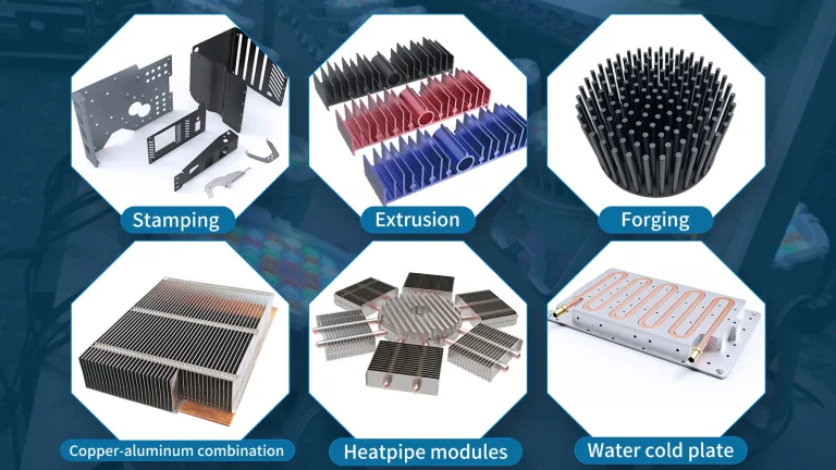
The thermal target must also fit a manufacturable geometry. Different heat sink processes support different combinations of fin thickness, height, density, base shape, tooling, and production volume.
| Heat sink type | Where it can fit | Design points to review |
|---|---|---|
| Extruded heat sink | Integrated base-and-fin profiles and repeatable cross-sections | Extrusion ratio, fin thickness, height-to-gap geometry, profile width, and secondary machining |
| Skived heat sink | Dense, thin fins formed from the same material as the base | Fin height, pitch, flatness, airflow pressure drop, and base dimensions |
| Zippered fin heat sink | Thin formed-fin stacks joined to a separate base | Fin pattern, joint quality, airflow direction, structural support, and assembly envelope |
| Folded fin heat sink | High area density using folded sheet material | Fin pitch, fold geometry, joining method, bypass control, and available fan pressure |
Early manufacturing review can prevent a thermally attractive concept from becoming impractical to produce. The drawing should define the heat source, keep-out areas, mounting features, airflow direction, envelope, material preference, and expected quantity.
6. A Practical Heat Sink Design Workflow
- Define the thermal requirement. Record total heat load, maximum allowable device or base temperature, worst-case inlet-air temperature, and available space.
- Choose the cooling regime. Decide whether the product will rely on natural convection or forced air, and identify orientation and enclosure restrictions.
- Create a first-pass geometry. Set base dimensions, fin length, height, thickness, count, and spacing within the manufacturing limits.
- Estimate fin efficiency and effective area. Use the material, geometry, and estimated heat-transfer coefficient to avoid treating all geometric area as equally active.
- Check airflow and pressure drop. For forced air, compare system resistance with the fan curve. For natural convection, confirm open vertical paths and adequate inlet and outlet vent area.
- Review the complete thermal path. Include the interface, base spreading, attachment joints, fin conduction, convection, and air-temperature rise.
- Verify the final design. Detailed thermal analysis and/or representative physical testing is recommended before relying on a design for a critical operating limit.
The calculators below are intended for early design estimates. They help establish requirements and compare options; they do not replace validation of the final assembly.
Frequently Asked Questions
What is heat sink fin efficiency?
Fin efficiency is the ratio of the heat a fin actually transfers to the heat it would transfer if its entire surface remained at the fin-base temperature. It reflects the temperature drop from the base toward the tip.
Does closer fin spacing always improve cooling?
No. Closer spacing adds fins and geometric area, but it can restrict airflow, merge boundary layers, and increase pressure drop. The result depends on the cooling mode, fan capability, geometry, and enclosure.
What is the best fin spacing for natural convection?
There is no single spacing that is best for every heat sink. It varies with fin height and length, temperature difference, orientation, available chimney path, and surrounding enclosure.
Why do tall fins sometimes provide limited improvement?
Tall fins add area, but the tip may operate at a lower temperature than the base. They can also create greater airflow resistance. When fin efficiency or airflow falls, part of the added area provides diminishing benefit.
Is copper always better than aluminum for a heat sink?
Copper conducts heat better, but it is heavier and generally more expensive. Aluminum often provides a better balance of conductivity, weight, manufacturability, and cost. The right choice depends on the heat-flux and mechanical requirements.
How does a fan affect the ideal fin spacing?
Higher available static pressure can support narrower channels and denser fin arrays. The choice should be based on the fan’s actual operating point against system resistance, not its free-air flow rating.
What information is needed to size a custom heat sink?
Useful inputs include heat load, allowable device or base temperature, ambient or inlet-air temperature, heat-source size and location, available envelope, airflow direction and fan data, mounting details, orientation, material preferences, and expected quantity.
Can an online estimator guarantee the final device temperature?
No. An estimator provides a first-pass engineering target. Final temperature also depends on component resistance, interfaces, spreading, bypass airflow, enclosure conditions, manufacturing tolerances, and the actual operating environment.
Turn Your Thermal Target Into a Manufacturable Heat Sink
Ecotherm has 22 years of custom heat sink manufacturing experience and supports low-volume projects with an MOQ starting from one piece. Share your drawing, heat load, temperature target, available space, and airflow conditions for a free drawing feasibility review and custom cooling-solution recommendation.