Forced-air cooling design tool
Pressure Drop & Fan Selection Calculator
Estimate how much static pressure a fan must overcome to push the target airflow through a heat sink, duct and accessories—then screen a candidate fan at the real system operating point.
1How restrictive is the heat sink fin channel?
2How much pressure do ducts, bends and filters add?
3Will the selected fan still deliver the target airflow?
See the complete airflow path — pressure losses add along the series path
Fan arrayCandidate curve
Duct + accessories— Pa
Skived heat sink— Pa
Core airflow: the air that must pass between the fins to remove heat.
Total fan airflow: core airflow plus the entered bypass/leakage allowance.
Duty point: target fan airflow at the calculated static-pressure requirement.
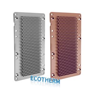
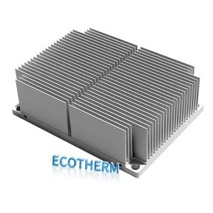
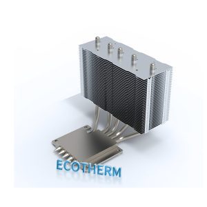
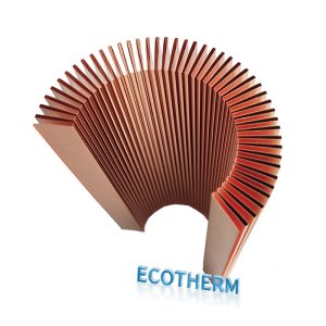
Choose the heat sink construction
Skived design focus: Do not select a fan from its free-air CFM alone. Dense skived fins move the duty point toward the high-static-pressure part of the fan curve.
Fan selection result
Skived heat sink system
Heat sink pressure drop
—
Fin-channel lossDuct + accessory loss
—
Straight duct, bends, filter and guardsRequired fan static pressure
—
Includes selection reserve—
—
Fan curve vs. system resistanceEstimated curve from entered endpoints
Target duty point—
Fan pressure at target—
Predicted operating airflow—
Pressure-loss budget at target airflow
Heat sink core
—
Straight duct
—
Bends
—
Filter + grille + other
—
Core face velocity—
Core Reynolds number—
Core flow regime—
Hydraulic diameter—
Usable open area—
Total fan airflow—
Air density—
Pressure reserve at target—
Selection boundary: use the manufacturer's full fan curve at the intended voltage, speed and air density before purchasing. Endpoint fitting cannot reproduce stall regions, electronic control limits, acoustic behavior or installation system effects.
For a final forced-air design review, share the heat load, permitted temperatures, heat-sink envelope, fan datasheet/curve, enclosure drawing and obstruction layout. Ecotherm can review manufacturability and propose a custom skived, extruded, zippered-fin or folded-fin heat sink.