Vapor Chamber vs. Heat Pipe: The Engineer's Guide to Upgrading Thermal Designs

When designing thermal solutions for high-performance processors, ASICs, or IGBTs, engineers inevitably face a critical decision: stick with traditional heat pipes or upgrade to a Vapor Chamber (VC).
Both are highly efficient two-phase cooling devices that utilize the latent heat of vaporization. However, they manage heat distribution in fundamentally different ways. Relying solely on total TDP (Thermal Design Power) is a mistake; the decision must be driven by heat flux, spatial constraints, and hot spot severity.
Quick Reference: Heat Pipe vs. Vapor Chamber
| Feature | Heat Pipe | Vapor Chamber |
| Heat Transfer Path | 1-Dimensional / Linear | 2-Dimensional / Planar |
| Hot Spot Mitigation | Moderate | Excellent – eliminates severe hot spots |
| Heat Flux Limit | Typically up to 50-75 W/cm² | Can handle >150 W/cm² |
| Form Factor / Z-Height | Requires bending/routing space | Ultra-low profile, can act as the direct base |
| Tooling Cost | Low/Standard | Higher – custom stamping and sintering required |
The Core Difference: 1D vs. 2D Heat Spreading
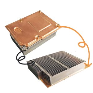
A standard copper heat pipe transfers heat linearly (1D) along its axis. To cool a large surface, multiple heat pipes are usually embedded into an aluminum or copper base plate. However, the base plate itself has thermal resistance, which can cause localized heat buildup before the thermal energy even reaches the embedded pipes.
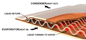
A Vapor Chamber transfers heat in two dimensions (2D). It acts as the entire base of the heat sink. The moment the fluid vaporizes above the heat source, the vapor rapidly spreads across the entire internal planar cavity, distributing heat evenly to the attached fins. This isothermal behavior effectively nullifies spreading resistance.
3 Engineering Triggers: When MUST You Upgrade to a VC?
At Ecotherm, we review hundreds of thermal designs annually. We recommend upgrading to a Vapor Chamber when your design hits one or more of the following thresholds:
1. Extreme Heat Flux (The >100 W/cm² Rule)
As silicon dies shrink but power increases, total TDP becomes less relevant than Heat Flux (power per unit area). When a small die generates massive heat—exceeding 75 to 100 W/cm²—traditional heat pipes may reach their capillary limit or boiling limit, causing dry-out and catastrophic failure. A VC’s massive internal evaporation area easily absorbs extreme localized heat fluxes.
Send us your project to receive free project evaluation suggestions!
2. Severe Spatial Constraints (Z-Height Limits)
Heat pipes are typically cylindrical (e.g., 6mm or 8mm) and can be flattened, but flattening them too much destroys their internal capillary wick, severely degrading performance. If your server chassis or telecom enclosure demands a highly restricted Z-height, a custom stamped Vapor Chamber can be designed as thin as 3.0mm while still serving as the structural base for the fin array.
3. Maximum Fin Utilization
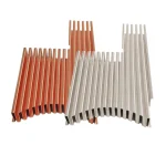
In forced convection air cooling, fins located directly above the heat pipes do most of the work, while perimeter fins remain underutilized. Because a vapor chamber creates a perfectly isothermal base, it ensures that every single fin—even those at the far edges of a large Skived Fin or Zipper Fin assembly—receives an equal amount of heat, maximizing the efficiency of your airflow.
The Manufacturing Reality: Balancing Cost and Performance
Upgrading to a vapor chamber is an engineering necessity for high-end systems, but it involves higher NRE (Non-Recurring Engineering) and tooling costs due to custom stamping, specialized sintered wick deposition, and vacuum sealing.
For intermediate designs (e.g., 150W – 300W with moderate die sizes), a well-designed Heat Pipe Cooling Module with an optimized copper base might still be the most cost-effective route. However, as you push toward 500W+ in compact footprints, the thermal budget leaves no room for spreading resistance, making the VC a mandatory investment.
Get Expert DFM Validation for Your Thermal Design
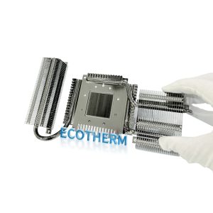
Do not guess which two-phase cooling technology is right for your project. The most effective high-power heat sinks often combine technologies—such as a custom Vapor Chamber base topped with high-density Skived Fins manufactured via precision CNC.
Upload your CAD/STEP files today. Ecotherm’s engineering team will evaluate your heat flux, spatial limits, and budget to provide a Free Thermal DFM (Design for Manufacturing) analysis within 24 hours. We offer a low MOQ of just 1 piece to accelerate your thermal validation phase.
FAQ: Frequently Asked Questions
1. What is the minimum thickness for a custom vapor chamber?
For standard industrial applications, we recommend a minimum thickness of 3.0mm to allow for a robust sintered wick structure and internal support columns. However, for mobile or ultra-compact designs, we can manufacture ultra-thin vapor chambers down to 0.4mm using specialized etched-wick manufacturing processes.
2. Can you repair a damaged vapor chamber?
No. A vapor chamber is a vacuum-sealed vessel. If the copper envelope is punctured or cracked, the vacuum is lost, and the working fluid will dry out, rendering the device useless (it effectively becomes a piece of solid copper). This is why our factory performs 100% Helium Leak Testing and thermal performance checks before shipping to ensure every unit is hermetically sealed.
3. How does a Vapor Chamber compare to a solid copper heat spreader?
A vapor chamber is significantly lighter and more conductive than solid copper. While copper has a thermal conductivity of ~400 W/m·K, a vapor chamber has an effective conductivity (Keff) of 5,000 to over 20,000 W/m·K depending on the power load. This means it spreads heat 10x to 50x faster than solid copper, eliminating hotspots much more effectively.