Custom Vapor Chamber Manufacturing: A Complete DFM Guide for Engineers
Introduction
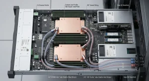
Standard vapor chamber designs are no longer sufficient for many high-power applications. As heat flux increases and layouts become more complex, off-the-shelf solutions fail to deliver consistent thermal performance.
Custom vapor chamber design is now common, but many projects fail not because of thermal theory, but because of manufacturing mismatch.
Designs that look feasible in simulation often cannot be manufactured reliably, or cannot maintain consistency in mass production.
This is where DFM becomes critical:
DFM (Design for Manufacturability) directly determines thermal performance, reliability, and yield.
This guide focuses on the practical constraints engineers must consider when designing a custom vapor chamber.
What Is DFM in Vapor Chamber Design?
DFM Definition in an Engineering Context
Design for Manufacturability dictates that physical layout and thermal parameters must account for the constraints of pressing, sintering, and vacuum brazing equipment. DFM shifts the focus from “can it be built once?” to “can it be mass-produced with absolute thermal consistency?”
Why Vapor Chambers Heavily Rely on DFM
Unlike a solid aluminum heat sink, a vapor chamber relies on a hidden, enclosed two-phase system.
Zero Visibility: The critical components (the wick and vapor space) are sealed.
Irreparability: Once vacuum-sealed and charged with working fluid, structural or capillary failures cannot be reworked.
Performance Dependency: Thermal performance is entirely dictated by the structural integrity of the internal cavity under high pressure and temperature variations.
Internal Wick Structure: Sintered Powder vs. Mesh
Selecting the correct internal wick is the most critical DFM decision. It directly dictates the capillary pumping limit and the maximum heat flux the chamber can handle before dry-out occurs.
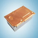
Sintered Powder Wick
Characteristics: Copper powder fused under high temperature, creating an isotropic porous structure.
Advantages: Generates extremely high capillary force. Exhibits superior liquid return capabilities, making it the default choice for combating severe, concentrated hotspots.
Limitations: Higher manufacturing cost. The sintering process requires precise temperature and atmospheric control to ensure uniform porosity.
Internal Wick Structure: Sintered Powder vs. Mesh
Selecting the correct internal wick is the most critical DFM decision. It directly dictates the capillary pumping limit and the maximum heat flux the chamber can handle before dry-out occurs.
Sintered Powder Wick
Characteristics: Copper powder fused under high temperature, creating an isotropic porous structure.
Advantages: Generates extremely high capillary force. Exhibits superior liquid return capabilities, making it the default choice for combating severe, concentrated hotspots.
Limitations: Higher manufacturing cost. The sintering process requires precise temperature and atmospheric control to ensure uniform porosity.
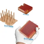
Mesh Wick
Characteristics: Woven copper wire layers diffusion-bonded to the internal chamber walls.
Advantages: High permeability (low resistance to liquid flow). Cost-effective and relatively simple to fabricate and scale.
Limitations: Generates lower capillary pumping force. Inadequate for extreme heat flux applications where rapid liquid replenishment is demanded.
Performance Comparison
| Parameter | Sintered Powder | Mesh |
| Capillary Force | High | Medium |
| Permeability | Medium | High |
| Max Heat Flux Capability | High | Moderate |
| Manufacturing Complexity | High | Low |
Engineering Conclusion
For high heat flux applications (>50 W/cm²), prioritize sintered structures. For cost-sensitive, large-area applications with moderate heat flux, a mesh wick is viable. Currently, hybrid wicks (combining sintered powder over the evaporator and mesh across the condenser) represent the optimal DFM trend for balancing cost and performance.
Internal Wick Structure: Sintered Powder vs. Mesh
Selecting the correct internal wick is the most critical DFM decision. It directly dictates the capillary pumping limit and the maximum heat flux the chamber can handle before dry-out occurs.
Sintered Powder Wick
Characteristics: Copper powder fused under high temperature, creating an isotropic porous structure.
Advantages: Generates extremely high capillary force. Exhibits superior liquid return capabilities, making it the default choice for combating severe, concentrated hotspots.
Limitations: Higher manufacturing cost. The sintering process requires precise temperature and atmospheric control to ensure uniform porosity.
Mesh Wick
Characteristics: Woven copper wire layers diffusion-bonded to the internal chamber walls.
Advantages: High permeability (low resistance to liquid flow). Cost-effective and relatively simple to fabricate and scale.
Limitations: Generates lower capillary pumping force. Inadequate for extreme heat flux applications where rapid liquid replenishment is demanded.
Performance Comparison
| Parameter | Sintered Powder | Mesh |
| Capillary Force | High | Medium |
| Permeability | Medium | High |
| Max Heat Flux Capability | High | Moderate |
| Manufacturing Complexity | High | Low |
Engineering Conclusion
For high heat flux applications (>50 W/cm²), prioritize sintered structures. For cost-sensitive, large-area applications with moderate heat flux, a mesh wick is viable. Currently, hybrid wicks (combining sintered powder over the evaporator and mesh across the condenser) represent the optimal DFM trend for balancing cost and performance.
Key Manufacturing Limits You Must Know
Designing outside the factory’s process window guarantees prototype failure.
Thickness Tolerance
Standard Range: ±0.05 mm to ±0.15 mm after pressing and sealing.
Impact: Tight tolerances are required to maintain the internal vapor space volume. Excessive compression during stamping crushes the wick, while insufficient compression weakens structural rigidity.
Maximum Size Capability
Constraints: Limited by the tonnage of stamping presses and the volumetric capacity of vacuum brazing furnaces.
Large-Format Risks: Chambers exceeding 300mm x 300mm face severe risks of structural warping (oil-canning) and internal fluid distribution non-uniformity during operation.
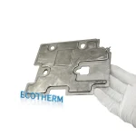
Flatness Control
Flatness directly impacts interfacial thermal resistance. A bowed chamber will create micro-gaps when mated to a liquid cold plate or external heat sink, requiring thick layers of thermal grease (TIM) that negate the chamber’s high conductivity.
Vacuum Brazing & Sealing Reliability
Core Metrics: Leak rate testing via helium mass spectrometry. Long-term hermeticity is non-negotiable.
Variables: Sealing reliability depends on strict temperature profiling during brazing, material expansion matching, and outgassing procedures to eliminate non-condensable gases (NCGs).
Yield Considerations
Complex geometries (stepped bases, extreme cutouts) exponentially drop manufacturing yield. Implementing DFM early optimizes the shape for standard tooling, separating professional foundries from standard workshops.
Common Design Mistakes in Custom Vapor Chambers
Ignoring Wick Selection
Mismatching the wick to the thermal load results in dry-out (liquid fails to return to the evaporator) and an immediate spike in thermal resistance.
Over-Optimizing Geometry
Pushing for an ultra-thin profile (<0.4mm) without structural support pillars causes the chamber to collapse under atmospheric pressure. Conversely, oversized chambers suffer from internal vapor starvation.
Underestimating Interface Resistance
The internal efficiency of a vapor chamber is wasted if the external mounting pressure and surface finish are not optimized to minimize contact resistance with the heat source.