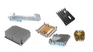
Vapor Chamber Heat Sink: Heat Spreading, Data & Selection Guide

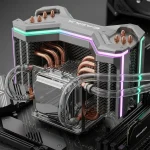
A vapor chamber heat sink is used when a small high-power component creates a local hot spot that a standard heat sink base cannot spread evenly. The vapor chamber spreads heat across the base, while the fins dissipate that heat into air or liquid flow.
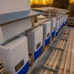
This type of thermal system is common in GPUs, AI servers, power electronics, IGBT modules, laser systems, and compact electronics where heat flux, space limits, and temperature uniformity are critical.
What Is a Vapor Chamber Heat Sink?
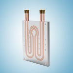
A vapor chamber heat sink combines a sealed vapor chamber with a fin structure. The vapor chamber works as a flat heat spreader. The fins work as the heat dissipation area.
Inside the vapor chamber, a small amount of working fluid evaporates at the hot zone, moves as vapor to cooler areas, condenses, and returns through the wick structure.
Key engineering data
| Item | Typical value / design point | Why it matters |
|---|---|---|
| Heat spreading direction | 2D planar spreading | Reduces local hot spots |
| Common material | Copper | High thermal conductivity |
| Working fluid | Water in most copper chambers | Efficient phase-change transfer |
| Wick structure | Sintered copper / mesh / composite | Controls liquid return |
| Common thickness | 0.4–5.0 mm depending on application | Affects capacity and mechanical strength |
| Typical use | High heat flux, compact space, uneven heat source | Where solid bases are not enough |
How Do Vapor Chamber Cooling Systems Work?
A vapor chamber cooling system uses a passive phase-change cycle.
- Evaporation: Heat enters the chamber from the chip or module.
- Vapor spreading: The working fluid evaporates and spreads through the internal cavity.
- Condensation: Vapor reaches cooler areas and releases heat.
- Liquid return: The wick structure returns condensed liquid to the heat source.
Heat transfer process
| Step | What happens | Engineering result |
|---|---|---|
| 1 | Heat enters the evaporator zone | Local hot spot is absorbed |
| 2 | Fluid evaporates | Heat is carried by phase change |
| 3 | Vapor spreads across the chamber | Temperature becomes more uniform |
| 4 | Vapor condenses | Heat is released to the base and fins |
| 5 | Liquid returns through wick | Passive continuous cycle |
Vapor Chamber vs Heat Sink: What Is the Difference?
A traditional heat sink mainly relies on solid conduction through the base and convection through the fins. A vapor chamber heat sink adds a heat spreading layer before heat reaches the fins.
The difference becomes important when the heat source is much smaller than the heat sink base.
| Comparison | Traditional heat sink | Vapor chamber heat sink |
|---|---|---|
| Main function | Heat dissipation | Heat spreading + dissipation |
| Heat transfer mode | Solid conduction | Phase-change spreading + fin convection |
| Hot spot control | Moderate | Strong |
| Best heat source | Larger contact area | Small, dense, high-power source |
| Base temperature uniformity | Lower | Higher |
| Cost | Lower | Higher |
| Manufacturing complexity | Lower | Higher |
Practical rule:
If the heat source is large and the power density is moderate, a standard heat sink may be enough. If the heat source is small and the center temperature is too high, a vapor chamber heat sink is usually a better option.

Heat Pipe vs Vapor Chamber: Which Should You Choose?
The main difference is heat direction.
A heat pipe moves heat mainly in one direction, from a hot area to a remote fin stack.
A vapor chamber spreads heat in two dimensions across a flat surface.
| Design question | Better choice |
|---|---|
| Need to move heat to a remote fin stack? | Heat pipe |
| Need to spread heat under a large fin area? | Vapor chamber |
| Heat source is small and dense? | Vapor chamber |
| Space is long and narrow? | Heat pipe |
| Multiple chips on one base? | Vapor chamber |
| Need both spreading and remote transfer? | Vapor chamber + heat pipes |
Data comparison
| Specification | Solid copper base | Heat pipe assembly | Vapor chamber heat sink |
|---|---|---|---|
| Effective thermal conductivity | ~400 W/m·K | Often several thousand W/m·K | Often several thousand W/m·K |
| Heat transfer direction | 3D solid conduction | Mainly 1D transfer | Mainly 2D spreading |
| Hot spot reduction | Medium | Medium to high | High |
| Cost level | 1× | 1.5–2× | 3–5× |
| Best use case | General cooling | Remote heat transport | Local hot spot spreading |
Sintered Copper Vapor Chamber Heat Sink: Why the Wick Matters
A sintered copper vapor chamber heat sink uses a porous copper wick inside the chamber. This wick returns condensed liquid to the heat source by capillary action.
The wick is one of the most important parts of the vapor chamber. If liquid cannot return fast enough, the chamber may dry out and thermal resistance will increase.
| Wick type | Advantage | Limitation | Best use |
|---|---|---|---|
| Sintered copper powder | Strong capillary force | Higher process cost | High heat flux and compact systems |
| Copper mesh | Good balance of cost and performance | Lower capillary force | Thin chambers and moderate power |
| Grooved wick | Lower cost | More orientation-sensitive | Simple spreading applications |
| Composite wick | Tunable performance | More complex process | High-end custom thermal systems |
For industrial, server, and power electronics applications, sintered copper wicks are often preferred when heat flux is high or orientation may change.
Vapor Chamber Thermal Conductivity: What Data Should Engineers Check?
Vapor chamber thermal conductivity is usually described as effective thermal conductivity. It is not the same as the thermal conductivity of solid copper or aluminum because the vapor chamber uses evaporation and condensation.
Do not evaluate a vapor chamber only by one conductivity number. Ask for the test condition.
| Parameter | Why it matters | What to ask |
|---|---|---|
| Effective thermal conductivity | Shows spreading ability | What test size and power? |
| Thermal resistance | Directly affects component temperature | Rth from source to base or source to air? |
| Heat source size | Determines spreading resistance | What chip size was tested? |
| Heat load | Determines capacity | Tested at 50 W, 200 W, or 500 W? |
| Chamber thickness | Affects vapor space and stiffness | Minimum and recommended thickness |
| Wick type | Controls liquid return | Sintered, mesh, groove, or composite |
| Orientation | Affects liquid return | Horizontal, vertical, inverted test data |
| Flatness | Affects contact resistance | Flatness tolerance after manufacturing |

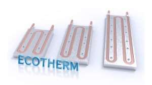
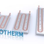
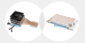
Vapor Chamber + Pass-Through Heatsink Fins: When Does It Make Sense?
A vapor chamber + pass-through heatsink fins design is useful when the system needs both high heat spreading and strong air-side dissipation.
In this structure, the vapor chamber works as the base heat spreader, while fins are attached, soldered, crimped, or integrated close to the chamber surface. The goal is to reduce interface loss and use more fin area effectively.
| Hybrid design | Why use it | Typical application |
|---|---|---|
| Vapor chamber + skived fins | High fin density | GPU, AI accelerator, compact server |
| Vapor chamber + zipper fins | Lightweight fin stack | Server module, telecom equipment |
| Vapor chamber + extruded fins | Cost-controlled structure | Medium-power electronics |
| Vapor chamber + heat pipes | Spreading + remote transfer | Complex internal layouts |
| Vapor chamber + liquid cold plate | Very high power | AI server, IGBT, laser systems |
This design is especially relevant for high-power electronics where a standard base cannot spread heat fast enough and airflow is limited by the mechanical layout.
3D Vapor Chamber: When Is It Needed?
A 3D vapor chamber is used when heat must move through a more complex structure than a flat plate. It can help when the heat source, base, and fin stack are not aligned in a simple flat layout.
Compared with a flat vapor chamber, a 3D vapor chamber can improve packaging flexibility, but it also increases manufacturing complexity, sealing risk, and cost.
| Type | Heat spreading | Complexity | Typical use |
|---|---|---|---|
| Flat vapor chamber | 2D planar spreading | Medium | GPU, CPU, AI module |
| Ultra-thin vapor chamber | Thin 2D spreading | High | Laptop and compact electronics |
| 3D vapor chamber | Multi-direction spreading | Very high | Advanced compact systems |
| Vapor chamber + heat pipe | 2D spreading + 1D transport | High | Remote fin stack designs |
Use 3D vapor chambers only when a flat chamber or heat pipe design cannot meet space or temperature requirements.
How to Choose a Vapor Chamber Thermal System
Start with the thermal problem, not the product name.
If you need to move heat, consider heat pipes.
If you need to spread heat, consider a vapor chamber.
If you need to remove very high heat with liquid, consider a liquid cold plate.
Data to prepare before requesting a custom design
| Required data | Example |
|---|---|
| Heat source size | 20 × 20 mm chip, 35 × 35 mm module |
| Power / TDP | 100 W, 300 W, 800 W |
| Maximum temperature | Junction, case, or surface limit |
| Available space | Length, width, height |
| Airflow | Natural convection, fan airflow, ducted airflow |
| Mounting pressure | Screw locations, clamping force |
| Material preference | Copper, aluminum, hybrid |
| Fin type | Skived, zipper, extruded, folded fin |
| Quantity | Prototype, pilot run, mass production |
| Reliability test | Leak test, thermal cycling, corrosion resistance |
Quick selection guide
| Project condition | Recommended solution |
|---|---|
| Low-to-medium power, cost-sensitive | Aluminum heat sink |
| Need high fin density | Skived heat sink |
| Need remote heat transport | Heat pipe heat sink |
| Local hot spot under a large base | Vapor chamber heat sink |
| Multiple chips on one compact module | Vapor chamber heat spreader |
| Very high power | Liquid cold plate |
| AI server module with forced airflow | Vapor chamber + skived / zipper fins |
| Laser or IGBT with high heat flux | Vapor chamber or liquid cold plate |
Questions Engineers Often Ask
How much can a vapor chamber reduce temperature?
It depends on heat source size, chamber size, airflow, mounting pressure, and fin structure. In many designs, the main benefit is reducing the temperature difference between the heat source area and the edge of the heat sink.
Can a vapor chamber cool multiple chips?
Yes, if the chamber size and wick structure are designed correctly. It is useful when multiple heat sources need a more uniform base temperature.
Can fins be soldered directly to a vapor chamber?
Yes, depending on the vapor chamber design and manufacturing process. Common options include soldering, brazing, crimping, or mechanical assembly.
When is a liquid cold plate better?
A liquid cold plate is better when air cooling cannot remove the required heat, especially in high-power AI, IGBT, laser, and battery systems.
What information should be sent to Ecotherm?
Send the drawing, 3D file, heat source size, power, available space, airflow condition, material preference, and expected quantity.
FAQ
Is a vapor chamber better than a heat sink?
Yes, when heat spreading is the bottleneck. A vapor chamber spreads local heat across a larger base area. A standard heat sink is still better for cost-sensitive, lower-power designs.
What is a vapor chamber heat sink used for?
It is used for compact high-power electronics. Common applications include GPUs, AI servers, power modules, IGBT systems, lasers, telecom equipment, and industrial electronics.
Is a vapor chamber the same as a heat pipe?
No. A heat pipe moves heat mainly in one direction. A vapor chamber spreads heat across a flat plane. Both use phase-change heat transfer.
What is a sintered copper vapor chamber heat sink?
It is a vapor chamber heat sink with a sintered copper wick. The wick helps liquid return to the hot area, which supports stable cooling under high heat flux.
Can a vapor chamber replace a heat sink?
No, not by itself. A vapor chamber spreads heat, but the system still needs fins, airflow, chassis contact, or liquid cooling to dissipate that heat.
When should I choose vapor chamber cooling?
Choose it when the heat source is small, power density is high, space is limited, or the base temperature must be more uniform across a large fin area.