CUSTOM HEAT SINK, PERFECTED FOR YOU.

Table of Contents

Introduction to the Vapor Chamber (VC) Liquid Cooling Heat Dissipation and the Working Principle of VC Liquid Cooling Heat Dissipation

With the performance of mobile phone processors and the arrival of the 5G era, more data needs to be processed. The performance of mobile devices such as mobile phones is getting higher and higher, which also poses a greater challenge to the heat dissipation performance.


Most of the newly launched flagship phones and 5G mobile phones adopt VC liquid cooling for heat dissipation. Most students may not be familiar with VC liquid cooling heat dissipation. What are the differences between VC liquid cooling heat dissipation and heat dissipation by copper pipes? With these questions, let me introduce VC liquid cooling heat dissipation to you.
VC-liquid-cooling-on-mobile-phones

What Does VC Liquid Cooling Heat Dissipation Mean?

VC liquid cooling (Vacuum Chamber Vapor Chamber technology, with the English name Vapor Chamber) is also known as an isothermal plate, a heat spreader, etc. It is a highly efficient way to transfer heat.
It was initially a heat dissipation solution provided by a heat dissipation manufacturer, Celsia, for AMD’s high-end graphics cards to replace heat pipe heat dissipation.
Currently, the common VC vapor chambers (taking copper VC as an example):
 

1, Slice Chamber:

 
The copper pipe is flattened, and a capillary structure and a support framework are inserted inside, with both sides welded and sealed.
VC liquid-cooled heat dissipation vapor chamber

2.Conventional VC (large VC):

It is formed by using two upper and lower copper plates, adding a capillary structure and support pillars, and welding around.

VC-Heat-Dissipation-vapor-chamber-(Conventional-type)

3.Ultra-thin VC:

Generally formed by etching thin copper sheets and using a sintered mesh structure, and welded around.

HFC-ultra-thin-vapor-chamber

The working principle of VC liquid cooling:

Schematic diagram of the working principle of VC vapor chamber

The working principle of VC liquid cooling:

The base of the vapor chamber is heated, and the heat source heats the micro copper mesh evaporator – heat absorption.
The cooling liquid (pure water) is rapidly evaporated into hot air in a vacuum and ultra-low pressure environment (<104 Tor or less) – heat absorption.
The vapor chamber adopts a vacuum design, and the hot air circulates more rapidly in the micro copper mesh environment – heat conduction.
The hot air rises due to heat, dissipates heat after encountering the cold source on the upper part of the heat sink, and is re-condensed into a liquid – heat dissipation.
The condensed cooling liquid flows back to the evaporation source at the bottom of the vapor chamber through the capillary pipes of the micro copper structure – reflux. The refluxed cooling liquid is vaporized again after being heated by the evaporator and absorbs heat through the micro copper mesh pipes – heat conduction and heat dissipation, and this cycle repeats.
Internal structure explosion diagram of VC vapor chamber
Profile-of-Vacuum-Vapor-chamber
Anatomical-diagram-of-the-internal-structure-of-the-vc-liquid-cooled-vapor-chamber

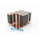
Similar to heat dissipation by copper pipes:


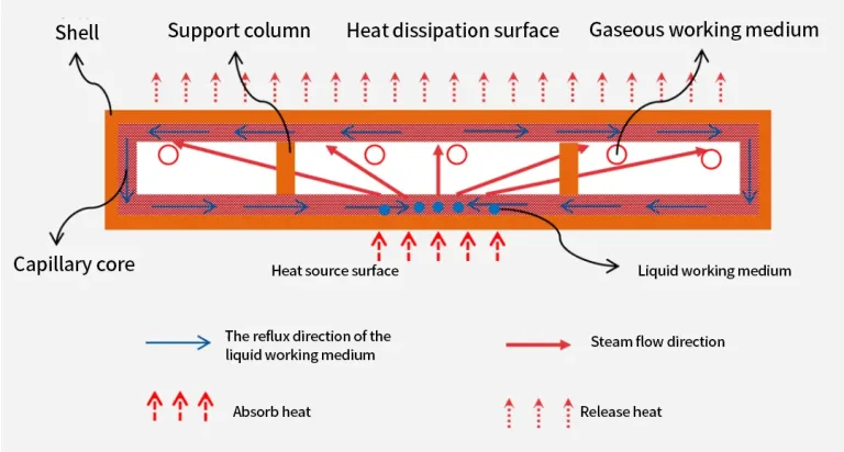
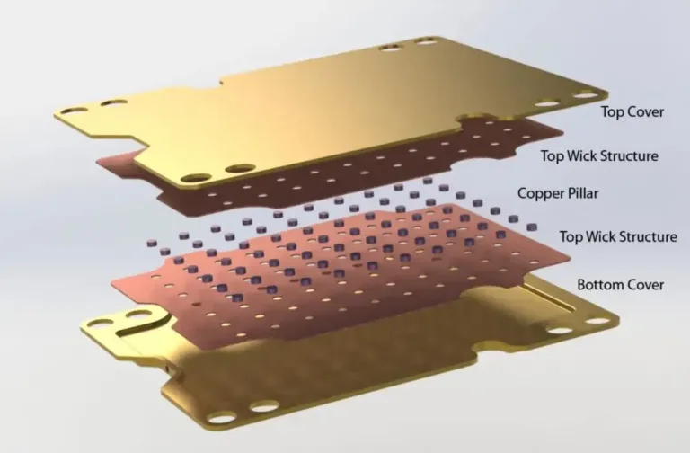
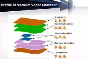
For VC liquid cooling heat dissipation, the inner wall of the vapor chamber is a capillary structure, and the interior is filled with liquid and evacuated. When heat is released, the internal liquid vaporizes and transfers to the condensation layer, where it is cooled and re-condenses into water. In this process, heat pipes and VC seem to be the same thing.


Differences between VC liquid cooling and heat pipes


Unlike heat pipes, in the production of VC vapor chamber products, the vacuum is first drawn and then pure water is injected to fill all the microstructures. Instead of using media such as methanol, alcohol, and acetone, degassed pure water is used, which can improve the performance and durability of the vapor chamber.

The combination of VC vapor chamber and heat pipes has the same basic principle and theoretical framework. The differences lie in dimensions, manufacturing methods, vacuum pumping, and water injection procedures, etc. In practical applications, the vapor chamber has advantages such as low extended thermal resistance, uniform heat flux, rapid heat diffusion, and light weight.

Cost: The heat pipe heat dissipation technology is relatively mature and the price is relatively low. VC vapor chamber dissipates heat faster, but the manufacturing cost is higher. It is generally used in electronic products with a small volume that require faster heat dissipation.
 

Conclusion:

VC liquid cooling heat dissipation (commonly known as the vapor chamber) and heat pipe heat dissipation both quickly conduct heat through the evaporation of the liquid. The manufacturing process of the VC vapor chamber is more complex and the cost is higher. However, it has a faster heat dissipation rate compared with heat pipes.

Need Custom Thermal Solutions ?

Free Design Support

Rapid Quoting

24h Quick Quotation

Free Thermal Evaluation

Sample MOQ for 1 pc

Send your 2D/3D CAD files (STEP, IGS, PDF) for a rapid technical review and quote.

Need a Custom Thermal Solution for Your AI Project?

Submit your CAD drawing or thermal requirements. Our engineers provide a rapid thermal evaluation within 24 hours.

About Ecothermgroup

Custom Heat Sink Manufacturer

At Ecothermgroup, we do more than manufacture heat sinks; we provide end-to-end thermal engineering solutions. Backed by over two decades of manufacturing expertise, we partner with your engineering teams to solve complex thermal challenges. Whether you require a critical design review or a rapid shift from prototype to mass production, we ensure your high-power systems achieve optimal thermal performance with maximum cost-efficiency.

Our Service

Sample MOQ for 1 pc

Free Custom Design

Free Thermal Analysis

Best Price Guaranteed

24 Hours Feedback

Custom Heat Sink Types

custom zippered fin heatsink

*Reliable Thermal Transfer for Power Supplies and Telecom.

*Efficient Thermal Management for 1000W+ AI Chips.

custom vapor chamber heatsink

*Ultra-thin, High-Performance Heat Spreaders for Compact Spaces.

custom skived fin heatsink

*High-Density Skived Fins – Up to 3 Meters in Length.

You can find ECOTHERM On :

Related Insights

Featured Case Studies

CFD thermal contour map showing temperature distribution for 3800W EV charging cold plate
  • Application: 800V EV Charging Station

  • Heat Load: 3800W | Thickness: 12mm

  • Technology: Friction Stir Welding (FSW) + CFD Simulation

Latest Engineering Insights

Scroll to Top

contact Ecotherm

We are available to assist you via email. Please don’t hesitate to get in touch, and we will respond to your inquiry as soon as possible.


Email:  support@ecothermgroup.com

Follow us on YouTube | TikTok | LinkedIn
Stay connected with us for updates, news, and more!


Please fill out the form below, and we will get back to you as soon as possible.

Get a Custom DFM Review & Quote

Please email your 3D CAD files (STEP/IGES) and project details. Max attachment: 50MB

support@ecothermgroup.com

100% Secure & Confidential | NDAs Supported | MOQ: 1 Piece

support@ecothermgroup.com

Contact Ecotherm

Please upload your design or requirements, and our experts will provide a precise cooling solution tailored to your needs.