The Real Bottleneck of AI Compute: Breaking the 1000W Thermal Ceiling
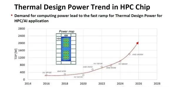
Let’s review the historical evolution of the maximum power consumption—Thermal Design Power (TDP)—for AI and HPC processors. A decade ago, in 2016, processor TDP was around 250W. By 2018, this figure increased to 300W (AMD MI50). Since then, TDP has grown exponentially: reaching 560W in 2021, 700W in 2023, 1000W in 2024, and is projected to hit an astounding 1400W by 2025.
The AMD MI350X can be viewed as the forced air-cooled version of the MI355X, featuring a TDP of 1000W. This clearly indicates that the current physical limit of traditional air cooling technologies is hovering right around the 1000W threshold.
AI and HPC processor maximum power consumption TDP growth from 2016 to 2025 based on TSMC data
The 1000W Air Cooling Wall: Why Traditional Methods Are Failing
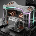
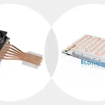
When dealing with processors approaching this 1000W limit, standard aluminum extrusions are completely obsolete. To maximize the potential of AI Cooling within the confines of air circulation, engineers must rely on advanced structures. A Skived Fin Heat Sink is often utilized to drastically increase the surface area within a confined space, while a high-performance Heat Pipe Cooling Module is integrated to rapidly transfer intense heat away from the core before the system throttles.
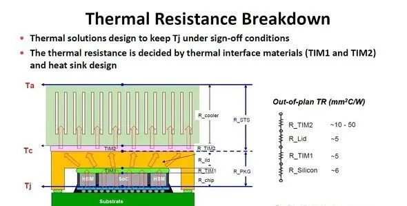
As TDP scales, we must consider how to dissipate the immense heat generated by SoCs (GPUs or AI processors) and High Bandwidth Memory (HBM) in advanced packaging like CoWoS, where the SoC and HBM are mounted on a silicon interposer.
The most common quantitative metric for heat transfer resistance is “thermal resistance” (°C/W), representing the temperature rise (°C) caused by unit power consumption (W). In thermal design, the fundamental principle is to keep the silicon PN junction temperature below a specific threshold (typically 70°C). Assuming the cooler ambient temperature is 25°C, the acceptable temperature difference is 45°C. In high-end server environments, cooling the ambient air to 20°C or lower is common, expanding the thermal budget to 50°C or more.
Cooling mechanisms of advanced CoWoS packaging and component thermal resistance analysis
Thermal Interface Materials (TIM) and the chosen cooling method are the primary factors dictating thermal resistance. The thermal resistance of TIM varies by material. Polymers have a higher resistance (10 to 50 mm²·°C/W), but as the TIM layer becomes thinner, resistance drops below 10. For metal-based TIMs, resistance drops significantly below 5. However, since the connected surfaces are never perfectly flat, managing the contact interface resistance is critical.
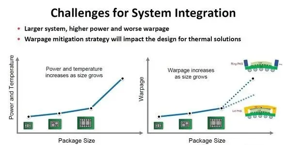
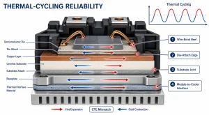
Another major challenge alongside increased power consumption is severe package warpage. To mitigate warpage, package housings are shifting from a traditional ring shape to a lidded design. This structural change significantly impacts the thermal architecture.
Transitioning from a ring to a lidded enclosure typically degrades cooling performance. In a ring configuration, the heat sink and silicon die (the heat source) are connected by a single TIM. In a lidded design, two TIM layers are required: one connecting the die to the lid (TIM1), and another connecting the lid to the heatsink (TIM2). This inherently increases the CoWoS thermal resistance, which theoretically lowers the maximum allowable TDP.
To counter this, modern thermal designs no longer attempt to dissipate heat uniformly across the entire silicon die. Instead, they optimize heat transfer paths specifically for localized high-heat areas (hot spots). To rapidly spread this intense localized heat across a broader surface area, integrating a Vapor Chamber Heat Sink into the base of the cooler has become a highly effective strategy, allowing lidded packages to handle even higher power loads than ring packages.
Package and heat sink co-optimization comparing uniform heat dissipation paths versus localized hot spot thermal management.
The Future Belongs to Liquid: Solutions for 1400W and Beyond
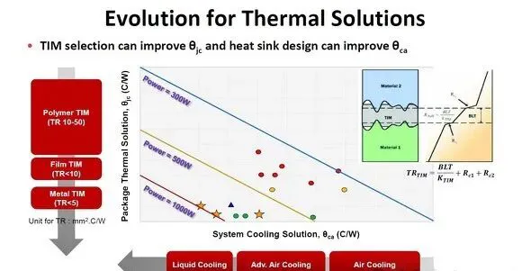
The power handling capacity of AI/HPC processors is ultimately dictated by the cooling technology. While forced air cooling is cost-effective, its thermal resistance is too high for next-generation chips.
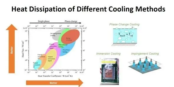
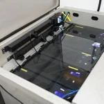
Water’s heat transfer coefficient is approximately 25 times that of air. When forced liquid cooling is still insufficient for extreme densities, engineers turn to Two-phase cooling (phase-change cooling), utilizing the massive latent heat absorbed when a liquid transitions into a gas.
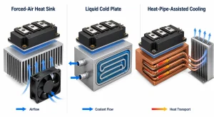
Performance comparison of various thermal technologies including air cooling, liquid cooling, and two-phase phase-change cooling.
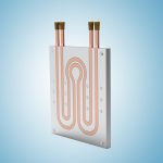
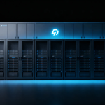
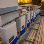
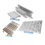
Currently, top-tier AI processors predominantly use forced liquid cooling. A non-conductive coolant flows through a cold plate, absorbing the processor’s heat. As a professional Liquid Cold Plate Manufacturer, Ecotherm precision-machines ultra-thin inner fins within the fluid channels to maximize the liquid-to-metal contact area, drastically enhancing thermal extraction.
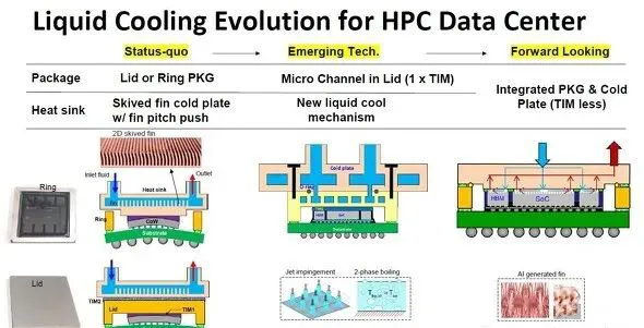
Looking forward, the next generation of cooling modules will route fluid directly through the package lid itself. This lid will feature a tightly integrated Micro-channel cold plate. Ultimately, the industry expects the cooling plate and the package to merge completely, eliminating the need for a separate TIM layer and breaking the thermal barrier once and for all.
Evolution of high-end AI processor forced liquid cooling modules featuring internal micro-channels and integrated packaging.
Custom Thermal Solutions from Design to Manufacturing
Are you developing high-power AI servers, power electronics, or HPC equipment? Do not let thermal resistance bottleneck your system’s performance. With 22 years of direct manufacturing experience, Ecotherm specializes in turning complex thermal challenges into reliable, mass-producible solutions.
Upload your CAD/STEP files today to get a Free Thermal DFM analysis from our engineering team within 24 hours. We proudly support a Custom Heat Sink Low MOQ of just 1 piece to accelerate your prototyping phase, ensuring 100% full inspection before your product ever leaves our facility.
At Ecothermgroup, we do more than manufacture heat sinks; we provide end-to-end thermal engineering solutions. Backed by over two decades of manufacturing expertise, we partner with your engineering teams to solve complex thermal challenges. Whether you require a critical design review or a rapid shift from prototype to mass production, we ensure your high-power systems achieve optimal thermal performance with maximum cost-efficiency.