Liquid Cold Plate Channel Design: Hydroforming, Stamping, and Micro-Channel Limits
You can design the most thermally efficient fluid channel in a CFD simulation, but if you cannot manufacture it at scale without excessive pressure drops, high tooling costs, or leakage risks, the design is useless.
The core of a custom liquid cold plate lies in how its internal fluid paths are formed. Different forming technologies directly dictate your routing freedom, maximum flow rate, and unit cost.
Before finalizing your CAD, you must align your channel geometry with the correct manufacturing process. Here is the engineering breakdown of the industry’s standard forming methods and micro-channel limits.
The Forming Showdown: Stamping vs. Hydroforming vs. Extrusion
For large-format battery packs or high-volume server racks, the base plate forming method is your primary cost driver.
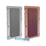
1. Stamping (The High-Volume Baseline)
The Engineering Reality: Utilizing servo presses capable of 60 strokes per minute, stamping is the undisputed choice for mass-producing small to medium-sized stamped liquid cold plates.
Parameters: Achieves a channel depth tolerance of ±0.05mm with material utilization exceeding 70%.
Trade-off: Channel geometries are limited by the drawing depth of the aluminum sheet. Sharp bifurcations are difficult to execute without tearing the material.
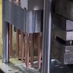
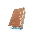
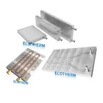
2. Hydroforming (The Complex Routing Expert)
The Engineering Reality: When your thermal load requires complex, branching, or serpentine structures to minimize Delta T, you must use a hydroformed cold plate.
Parameters: Liquid expansion pushes the aluminum blank into the die at 30-50 MPa (holding for 2-10 seconds). This massive pressure creates deep, highly customized fluid paths.
Trade-off: By optimizing the flow path freedom, hydroforming can reduce liquid pressure loss by 20% compared to stamped plates, making it ideal for massive 1200×800mm EV battery plates.
3. Extrusion (The Low-Cost Constraint)
The Engineering Reality: By forcing aluminum through a die to create pre-formed “harmonica tube” structures, extrusion cuts unit costs by up to 30% compared to stamping.
Trade-off: Strict linear constraint. You can only design straight flow paths. It is excellent for standard ESS (Energy Storage System) containers but completely unsuitable for high-density, targeted hotspot cooling.
Micro-Channel Machining: Tube-Embedded vs. Precision Etching
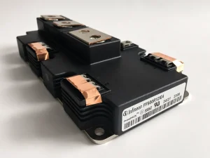
For localized high-heat-flux applications (like IGBTs or overclocked GPUs), standard forming is not enough. You must integrate micro-channels.
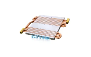
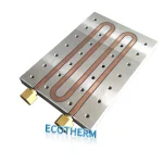
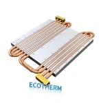
1. Tube-Embedded Cold Plates (The Zero-Leak Legacy)
The Process: Copper or stainless steel tubes are press-fit into a CNC-milled aluminum base (maintaining a depth-to-diameter ratio of ≤3:1) and secured via soldering or epoxy.
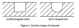
Pros & Cons: Because the fluid runs entirely inside a continuous metal tube, there are zero weld seams and zero leakage risks. However, a tube embedded cold plate suffers from poor routing flexibility (only simple U-shapes or serpentines) and carries a high risk of galvanic corrosion if the copper/aluminum interface is not properly treated.
2. EDM & Chemical Etching (Ultra-Thin & High-Density)
The Process: For extreme precision, manufacturers use Wire Electrical Discharge Machining (EDM) to achieve ±0.01mm tolerances for hard tooling. For ultra-thin plates (thickness ≤0.5mm), chemical etching (using NaOH solutions) is deployed to carve micron-level cold plate micro-channels.
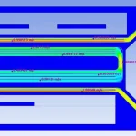
Engineering Advice: Optimize with Bionic Channels
Do not default to standard parallel channels. If you are struggling with a low Heat Transfer Coefficient (HTC), consider modifying your CAD to include bionic flow structures.
Shark-Fin / Bionic Structures: Adding specific bionic turbulence generators within the channel forces the coolant to mix continuously, breaking the thermal boundary layer and boosting the heat transfer coefficient by up to 15%.
Bifurcated Routing: Instead of standard 90-degree headers, reducing the branch angles (e.g., to 15°) drastically minimizes dead zones and lowers the overall temperature gradient across the plate.
Validate Your Thermal Design
Specifying the channel forming process is only half the battle. Once your flow path is stamped or hydroformed, it must be sealed permanently without warping the base plate.
Read our foundational guide: Liquid Cold Plate Manufacturing Guide: Materials & Trends
Next step in manufacturing: Liquid Cold Plate Welding: Vacuum Brazing vs. Friction Stir Welding (FSW)
Do not risk your thermal architecture on theoretical CFD data. If you have a complex micro-channel design, upload your STEP/IGES files to our engineering team. As a specialized custom liquid cold plate manufacturer, we will provide a rapid DFM review to ensure your channel geometry can be manufactured and sealed efficiently.