Solar Inverter Cooling Solutions: Custom Heat Sinks for High-Power PV Inverters
High-power PV inverters can become very hot during long operating hours, and excessive heat can reduce performance or even cause failure. This article looks at solar inverter cooling solutions, with a focus on custom heat sinks that help keep inverters safe, stable, and efficient. With the right cooling design from Ecothermgroup, solar systems can perform better and last longer.
Solar Inverter Heat Challenges
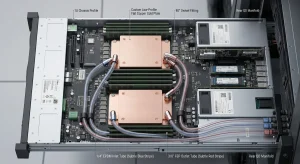
Solar inverter cooling is challenging because high-power PV inverters convert DC to AC through continuous switching and conduction losses. In real systems, IGBT cooling, MOSFET cooling, and diode thermal management all matter, because each device adds heat at the inverter power module level. Industry reports on PV inverter cooling show that compact cabinets with dense layouts often create uneven heat flux, so one hot spot can raise junction temperature faster than expected. That is why a solar inverter heat sink is not a simple add-on; it is part of photovoltaic inverter thermal management from the start.
In 2023, global solar PV capacity passed 1.4 TW, and utility-scale inverters are now expected to handle higher power in tighter spaces. This has pushed high-power inverter cooling toward custom heat sink for inverter designs rather than generic parts. Ecothermgroup and other thermal specialists often focus on lower thermal resistance, because every extra step in the heat path adds temperature rise. CFD thermal analysis and thermal simulation are widely used to test airflow, fin shape, and mounting before hardware is built, which helps reduce guesswork in power electronics cooling.
| Heat challenge | Why it happens | Cooling response |
|---|---|---|
| Hot spots near switches | Switching device heat dissipation is concentrated | Use a PV inverter heat sink with better fin coverage |
| Blocked airflow | Dust, ducts, or poor cabinet design reduce flow | Improve channels and monitor temperature |
| Fast temperature rise | High load and small thermal mass | Choose a heat sink for solar inverter with lower thermal resistance |
Why Inverters Run Hot
Inverters run hot because energy loss occurs both when devices conduct current and when they switch. A skived fin heat sink study on PV inverter IGBT arrays showed measurable temperature reduction compared with weaker heat spread paths, proving that fin geometry matters in compact designs. The same lesson applies to inverter heat sink selection: a larger surface area, good airflow, and a continuous thermal path help move heat away from the semiconductor device cooling zone before the junction temperature climbs too high.
In practice, aluminum is common because it balances cost, weight, and performance for solar inverter heat sink use. However, material alone is not enough. The package layout, mounting pressure, and thermal interface material also affect heat flux transfer. A typical best practice is to verify the full stack with CFD thermal analysis, especially when the inverter power module thermal management must support IGBT heat sink, diode thermal management, and MOSFET cooling in the same enclosure.
- Check airflow direction and fan blockage early
- Match fin density to dust and cabinet space
- Confirm contact pressure and interface quality
Impact on Power and Life
Heat does not only affect comfort; it reduces output and shortens service life. When junction temperature rises, the inverter may derate, lower efficiency, or shut down to protect itself. Field discussions around PV inverter cooling also show that temperature monitoring is standard because repeated overheating shortens capacitor, solder, and semiconductor life. In multi-duct systems, blockage diagnosis studies found that cooling performance can vary across inverter types, which means a thermal issue may appear as a slow power loss before a full failure.
That is why solar inverter cooling must be planned for the full service life, not just peak load. A custom heat sink for inverter use can improve hot spot reduction and keep the temperature rise stable under real site conditions. For safe operation, engineers should review thermal resistance targets, test under worst-case ambient temperature, and keep maintenance checks on dust, fan health, and duct flow. Reliable high-power inverter cooling protects both immediate power delivery and long-term system value.
Cooling Methods Overview
Effective solar inverter cooling is essential because power losses in IGBTs, MOSFETs, diodes, and other switching devices quickly raise junction temperature and create local hot spots. In high-power PV inverters, the usual goal is not to remove every bit of heat, but to keep thermal resistance low enough that inverter power module thermal management stays within safe limits. Industry testing and CFD thermal analysis show that improved heat spreading can reduce temperature rise by improving heat flux paths from the device to the enclosure and ambient air.
Ecothermgroup and other custom heat sink suppliers often focus on the same basic challenge: matching the cooling method to the inverter power level, enclosure space, and maintenance plan. In many commercial systems, a solar inverter heat sink is chosen first, then supported by fans, ducts, or liquid loops if the power density is too high for passive cooling alone. This is why PV inverter cooling is usually a system-level decision rather than a single-part choice.
Forced-Air Cooling
Forced-air cooling is the most common step up from natural convection in photovoltaic inverter thermal management. Research on skived fin heat sinks for IGBT arrays showed that high-aspect-ratio fins can improve heat transfer in compact layouts, which is useful when the inverter has limited volume. In practice, fans push air across the inverter heat sink, lowering thermal resistance and helping control temperature rise in power electronics cooling.
| Method | Best Use | Main Limit |
|---|---|---|
| Natural convection | Lower-power or fanless designs | Depends on ambient air movement |
| Forced-air cooling | Mid- to high-power inverter heat sink designs | Fan wear, dust, and blockage risk |
A practical advantage is hot spot reduction around IGBT cooling zones and diode thermal management areas. The main drawback is reliability: a blocked duct or weak fan can quickly reduce performance. A temperature-based health diagnosis study on multi-duct PV inverter cooling systems found that blockage detection is important for keeping cooling stable across different inverter types. For this reason, regular cleaning and airflow checks are part of standard high-power inverter cooling maintenance.
Liquid Cooling and New Options
Liquid cooling is used when a custom heat sink for inverter designs must handle very high power density or tight packaging. Compared with air systems, liquid loops can move heat away more evenly from the PV inverter heat sink and reduce dependence on room airflow. This is especially useful for top-side cooling and double-sided cooling, which are often discussed for modern inverter power module thermal management.
New options also include advanced materials, better thermal interface layers, and wider use of thermal simulation before production. These tools help engineers compare semiconductor device cooling choices and predict junction temperature more accurately. In many cases, a well-designed solar inverter heat sink with low contact thermal resistance can deliver strong results without adding a complex liquid circuit.
- Use forced-air cooling when service access is easy and dust control is manageable.
- Choose liquid cooling when power density is high and size limits are strict.
- Validate the design with CFD thermal analysis before final production.
In short, the best solar inverter cooling method depends on the balance between cost, reliability, and heat flux. A carefully sized heat sink for solar inverter applications, combined with the right airflow or liquid path, remains one of the most practical ways to protect switching devices and extend inverter life.
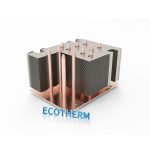
Custom Heat Sink Design
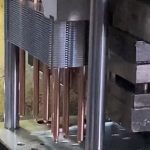
Custom heat sink design is a key part of solar inverter cooling because high-power PV inverters generate significant heat from IGBTs, MOSFETs, diodes, and power modules. In many PV inverter cooling systems, the main goal is to keep junction temperature within safe limits while reducing thermal resistance from the device to ambient air. Recent studies on skived-fin aluminum sinks for inverter IGBT arrays show that a well-designed fin structure can lower operating temperature by several degrees compared with simpler layouts, which supports better reliability in compact photovoltaic inverter thermal management.
In practice, a custom heat sink for inverter use is needed because inverter cases, airflow paths, and module positions vary widely. Standard parts often do not match the exact heat flux or mounting area, especially in high-power inverter cooling designs. Ecothermgroup and other engineers usually treat the heat sink as part of the full power electronics cooling chain, not as a stand-alone part, because good contact pressure, base flatness, and airflow control all affect hot spot reduction and temperature rise.
Skived Fin Structure
Skived fins are often chosen for a solar inverter heat sink when space is tight but the heat load is high. The fin walls can be made thin and tall, which increases surface area without adding too much weight. This is useful for inverter power module thermal management, where the goal is to remove heat from a small footprint around semiconductor device cooling points. In research on PV inverter cooling, skived fin sinks performed well because high-aspect-ratio fins improved heat transfer in a compact enclosure.
| Design option | Main benefit | Best use |
|---|---|---|
| Skived fin | High surface area in small space | Compact high-power inverter cooling |
| Extruded fin | Lower cost and easier production | Moderate heat flux designs |
| Liquid-cooled plate | Very low thermal resistance | Very high power density systems |
For switching device heat dissipation, skived fins also help keep airflow effective when the fan path is designed correctly. However, they work best when dust control and maintenance are planned, since dense fins can lose performance if blockage is not checked. Field and lab studies on multi-duct PV inverter cooling have also shown that blocked channels can quickly reduce system health, so a custom layout should allow cleaning and inspection.
Material and Surface Choices
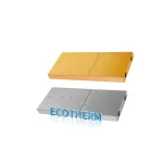
Material selection strongly affects inverter heat sink performance. Aluminum is common because it combines good conductivity, low weight, and practical cost, while copper is used when higher conductivity is needed in smaller zones. Surface finish also matters in power module cooling, since anodizing or protective coatings can improve corrosion resistance in outdoor PV sites. For diode thermal management and MOSFET cooling, the best design is usually one that balances conductivity, durability, and manufacturing cost.
- Aluminum: best for most solar inverter cooling projects
- Copper insert: useful for local hot spots and IGBT heat sink bases
- Anodized surface: better for corrosion resistance and long service life
Thermal simulation and CFD thermal analysis are now standard tools in photovoltaic inverter thermal management because they show how material choice changes heat flux spread and junction temperature. Common industry practice is to compare several base thicknesses, fin heights, and airflow speeds before final production. This reduces redesign risk and helps confirm that the custom heat sink for inverter use will still perform under real outdoor temperature rise conditions.
Fit for Compact PV Units
Compact PV units need custom heat sink design because enclosure volume is limited and cable, fan, and board placement can restrict airflow. In these cases, the heat sink for solar inverter systems must match the exact module position and the expected load profile. Natural convection is often not enough at higher power levels, so forced-air cooling is commonly selected for high-power inverter cooling, while liquid cooling may be used when heat density becomes extreme.
| Constraint | Design response | Result |
|---|---|---|
| Tight enclosure | Use compact skived fins or split sinks | Better fit and lower thermal resistance |
| High heat flux | Increase base thickness and airflow | Lower junction temperature |
| Outdoor exposure | Use coated aluminum and easy-clean gaps | Better durability and reliability |
A practical custom design should also support safe mounting, vibration resistance, and service access. A simple checklist is useful during selection:
- Confirm the device heat load and hot spot location.
- Match fin layout to the actual airflow path.
- Check mounting flatness and thermal interface quality.
For solar inverter cooling, the best custom heat sink is not simply the largest one; it is the one that fits the package, manages dust, and keeps the inverter stable over years of field use.
Monitoring and Failure Diagnosis
Effective solar inverter cooling depends on early monitoring, because thermal problems in PV inverter cooling often begin as a slow temperature rise before they lead to a shutdown. In high-power inverter cooling, sensors near the solar inverter heat sink, inverter power module, and IGBT heat sink help track junction temperature risk and support hot spot reduction. Field studies on skived-fin heat sinks show that high-aspect-ratio fins can lower device temperatures in compact PV inverter heat sink designs, which makes temperature data more useful for spotting weak airflow or increasing heat flux.
For photovoltaic inverter thermal management, the most useful checks are not only the absolute temperature, but also the trend over time. A gradual rise in temperature at the same load can point to higher thermal resistance, dirty fins, loose mounting, or degraded thermal interface material. Ecothermgroup custom heat sink for inverter designs often use this approach in power electronics cooling: compare inlet air, heat sink base, and device temperatures to identify whether the fault is in semiconductor device cooling, airflow, or contact quality.
| Symptom | Likely Cause | Diagnosis Action |
|---|---|---|
| Steady temperature drift | Airflow loss or dust buildup | Check fan path, fins, and filters |
| Fast local hotspot | Poor thermal contact | Inspect paste, pads, and mounting force |
| High module temperature | IGBT cooling or MOSFET cooling issue | Review thermal simulation and load balance |
Temperature-Based Checks
Temperature-based checks work best when they are tied to protection logic. In many systems, pre-alarm thresholds trigger derating before the inverter reaches a hard trip, which helps protect diode thermal management and switching device heat dissipation. Common practice is to place sensors close to the PV inverter heat sink and power module so a local rise is detected early, not after semiconductor stress has already increased.
Recent testing of PV inverter cooling systems also shows that better fin geometry can reduce the temperature rise under the same load. That is why thermal simulation and CFD thermal analysis are often used during design, then confirmed through live monitoring during operation.
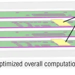
Blockage and Fault Detection
Blockage diagnosis is especially important in multi-duct or forced-air solar inverter cooling systems. A blocked channel, clogged fan, or uneven duct flow can create one hot zone while the rest of the inverter looks normal. Trend analysis helps here: if one duct area becomes hotter than the others, the problem is often blockage rather than total fan failure.
- Compare inlet and outlet temperatures across each cooling path.
- Check whether one heat sink section shows an abnormal temperature rise.
- Inspect fins, ducts, and fan speed for dust or wear.
- Verify sensor readings before replacing hardware.
For high-voltage PV inverter cooling, safe actions should include alert, derating, or shutdown when thermal faults persist. This approach supports reliable power module thermal management and reduces the chance of damage to IGBT cooling paths, inverter heat sink contact points, and other critical parts.
Design Trends and Future Outlook
In solar inverter cooling, the main design trend is higher power density in less space for heat removal. As 1500 V PV systems become more common, current can be reduced, but heat flux in the inverter power module can still rise because switching devices, diodes, and MOSFET cooling requirements are more demanding. This is why custom heat sink for inverter designs are shifting from general-purpose extrusions to tuned inverter heat sink shapes that control thermal resistance, junction temperature, and hot spot reduction more effectively. Ecothermgroup and similar suppliers now focus on heat sink for solar inverter designs that fit compact layouts while still supporting reliable high-power inverter cooling.
Research on skived fin heat sinks for IGBT arrays in PV inverters shows why geometry matters. High-aspect-ratio fins can lower temperature rise in tight enclosures, which supports better photovoltaic inverter thermal management when airflow is limited. In practice, this matches what many engineers prefer: passive air-cooled solutions for simplicity, or hybrid and liquid cooling when heat loads become too high. A common industry view is that reliability and lifecycle cost matter more than peak performance alone, especially for outdoor solar inverter cooling where dust, heat, and long service life are normal.
| Design Trend | Cooling Impact | Best Use |
|---|---|---|
| Skived fin aluminum | Lower thermal resistance and better heat dissipation | Compact PV inverter heat sink layouts |
| Top or bottom cooling integration | Improves inverter power module thermal management | New semiconductor package designs |
| Hybrid or liquid cooling | Handles higher heat flux | High-power inverter cooling in dense cabinets |
Wide-Bandgap Devices
Wide-bandgap semiconductors such as SiC and GaN are changing photovoltaic inverter thermal management because they switch faster and can reduce losses. That said, they do not remove the need for a strong solar inverter heat sink. Faster switching can shift heat into smaller areas, so semiconductor device cooling must handle local hot spots around IGBT cooling zones, diode thermal management points, and switching device heat dissipation paths. The future is not less cooling, but smarter power module cooling with lower thermal resistance from junction to ambient.
- Match the heat sink to the package, not only the total watt loss.
- Check junction temperature margins at high ambient temperatures.
- Use thermal simulation before freezing the mechanical design.
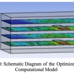
CFD and Thermal Optimization
CFD thermal analysis is becoming standard because it helps engineers spot airflow blockage, recirculation, and uneven heat flux before hardware is built. This is especially important for multi-duct inverter heat sink systems, where blockage can cause sudden temperature rise and reduced life. Temperature-based health diagnosis studies also show that monitoring cooling paths helps maintain performance over time, which supports predictive maintenance for PV inverter cooling systems.
The best future designs combine thermal simulation, practical testing, and easier maintenance access. For example, a custom heat sink for inverter can be tuned for fin spacing, base thickness, and fan placement, while still allowing cleaning and inspection in the field. A safe design rule is to verify performance under worst-case ambient and dust conditions, not only lab conditions. In the long run, solar inverter cooling will favor solutions that balance efficiency, manufacturability, and dependable operation across the full inverter life cycle.
People Also Ask
Why are custom heat sinks important for solar inverter cooling in high-power PV inverters?
High-power PV inverters generate a lot of heat from power semiconductors such as IGBTs, which can reduce efficiency and reliability if they are not managed properly. Custom heat sinks improve solar inverter cooling by matching the inverter’s layout, airflow, and heat load, helping keep critical components within safe operating temperatures.
How does a skived fin heat sink improve cooling performance in PV inverter applications?
A skived fin heat sink uses thin, high-aspect-ratio fins to increase surface area without taking up much space. This design can lower device temperatures more effectively in compact inverter systems, which is especially useful in dense PV inverter layouts.
How can cooling system blockage or degradation be diagnosed in PV inverter thermal systems?
Temperature-based monitoring can reveal abnormal patterns that point to airflow blockage, duct issues, or reduced cooling performance. Diagnostic methods compare expected and measured temperature behavior to identify whether the cooling path is healthy and still supporting reliable operation.
What are the latest trends in solar inverter heat dissipation design?
Current trends include improved forced-air and liquid cooling, advanced thermal materials, CFD-based thermal design, and the use of wide-bandgap semiconductors that generate less heat. These approaches are helping designers build more compact and efficient solar inverter cooling solutions from Ecothermgroup and other thermal specialists.
What is the best cooling method for a solar inverter?
The best method depends on inverter size, power level, and installation conditions. For many systems, forced-air cooling with a well-designed heat sink is sufficient, while larger or more compact high-power units may benefit from liquid cooling or custom thermal design.
How do I know if my solar inverter is overheating?
Common signs include reduced output, thermal derating, warning lights, alarms, or shutdowns during hot weather. If the inverter feels unusually hot or performance drops under load, the cooling system and heat sink should be checked.
Can a larger heat sink always improve solar inverter cooling?
Not always. A larger heat sink can help, but performance also depends on fin geometry, airflow, material choice, and how well the design fits the inverter enclosure. In many cases, a custom heat sink is more effective than simply increasing size.
What causes a solar inverter cooling system to fail over time?
Cooling systems can degrade due to dust buildup, blocked airflow paths, fan wear, thermal cycling, or poor maintenance. Over time, these issues reduce solar inverter cooling performance and can lead to higher component temperatures and lower reliability.