Heat Sink Structural Design Guide — Industry Heat Sink Design Specifications/Experience
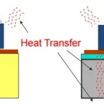
Considerations for Heat Sink Design:
The larger the surface area, the better the heat dissipation effect.
If the heat sink is placed in a way that promotes air circulation, heat dissipation efficiency can be improved.
Copper and aluminum are preferred materials due to their high thermal conductivity.
Increasing the thickness of the heat sink is more effective than increasing its length (based on our company’s experience).
Surface anodizing treatment can resist oxidation and corrosion, improve emissivity, and stabilize the heat dissipation performance.
The economic and practical feasibility of the manufacturing process.
Comparison of Heat Dissipation Performance Under Equal Conditions:
Light weight: Better performance.
Oxidized: Longer service life.
Non-oxidized: Shorter service life.
Grooved: Better heat dissipation performance.
Non-grooved: Poorer heat dissipation performance.
Higher fin density: Better heat dissipation (better with a fan).
Lower fin density: Poorer heat dissipation (better with a fan).
Higher fin height: Better heat dissipation (better with a fan).
Lower fin height: Poorer heat dissipation (better with a fan).
Thicker base: Higher heat absorption, but not necessarily better heat dissipation. Slightly better in comparison.
Thinner base: Lower heat absorption, but not necessarily worse heat dissipation. Slightly worse in comparison.
II. Principles for Choosing Heat Sinks
When selecting a heat sink, users must consider the following factors:
The module’s operating current size to determine the required heat dissipation area.
The operating environment, which will dictate the cooling method to be used—natural cooling, forced air cooling, or liquid cooling.
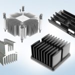
The shape and size of the device, and the available space for the heat sink, which will help determine the appropriate heat sink shape. Generally, most users opt for aluminum profile heat sinks.
III. Heat Sink Design Steps
Typically, the heat sink design process is divided into three steps:
Design the outline of the heat sink based on the relevant constraints.
Optimize the heat sink’s fin thickness, fin shape, fin spacing, and substrate thickness according to the relevant design guidelines.
Perform validation calculations.
Design Method for Natural Cooling Heat Sinks
In natural cooling, the temperature boundary layer is relatively thick. If the fin spacing is too small, the thermal boundary layers of two fins may intersect, affecting convection on the fin surfaces. Therefore, it is generally recommended that the fin spacing for natural convection heat sinks be greater than 12mm. If the height of the fins is less than 10mm, the fin spacing should be at least 1.2 times the fin height.
Natural convection heat sinks have weaker heat transfer capabilities on their surfaces. Adding corrugated fins will not significantly affect the natural convection performance, so it is advised not to use corrugated fins. For natural convection heat sinks, the surface is generally treated with black anodizing to increase the emissivity and enhance radiative heat transfer.
Since natural convection takes longer to reach thermal equilibrium, the substrate and fin thickness of the natural convection heat sink should be sufficient to withstand sudden thermal load shocks. It is recommended that the thickness be greater than 5mm.
If corrugated fins are added to the heat sink surface, the depth of the corrugations should generally be less than 0.5mm.
Increasing the number of fins in the heat sink is also recommended. Advanced international extrusion equipment and technology can achieve aspect ratios as high as 23:1, while in domestic applications, the maximum aspect ratio typically reaches 8:1.
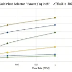
For environments where sufficient forced air cooling is provided, it is recommended to use cold plates formed by low-temperature vacuum brazing, with a minimum fin spacing of 2mm. A needle-like fin design can also be used to increase fluid disturbance and improve the convective heat transfer coefficient between fins.
When the airflow speed exceeds 1 m/s (200 CFM), the impact of buoyant forces on the surface heat transfer can generally be neglected.