What Are Heat Sink Cooling Systems and How Do They Work? (A B2B Engineering Guide)
Thermal management is the most critical bottleneck in modern electronics, from AI data centers to industrial motor drives. A poorly designed thermal module leads to hardware throttling and premature failure. This guide explains the engineering mechanics behind heat sink cooling systems and provides data-driven comparisons to help B2B engineers select the optimal thermal solution for high-TDP applications.
What Are Heat Sink Cooling Systems?
Heat sink cooling systems are engineered thermal management assemblies designed to absorb excessive heat from electronic components (such as CPUs, GPUs, or IGBTs) and dissipate it into a surrounding fluid medium, typically air or liquid.
Unlike basic metal blocks, industrial-grade cooling systems are precision-engineered to maximize surface area and minimize thermal resistance (theta JC and theta CA ). They act as a vital bridge, safely moving destructive heat away from sensitive silicon junctions before they exceed their maximum safe operating temperature (usually around 85°C to 105°C).
How Does a Heat Dispersal System Work? (The Physics of Cooling)
An effective heat dispersal system operates on three fundamental principles of thermodynamics. In high-power electronics, the efficiency of this process is heavily reliant on material selection and surface geometry.
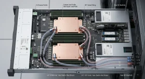
Conduction (Heat Absorption): Heat is generated by electrical resistance within the semiconductor. The base of the heat sink, directly contacting the chip via a Thermal Interface Material (TIM), absorbs this heat. Data point: Utilizing C1100 copper (thermal conductivity of 390 W/m·K) at the base absorbs heat nearly twice as fast as AL6063 aluminum (200 W/m·K).
Internal Spreading (Phase Change & Conduction): In advanced systems, heat doesn’t just travel through solid metal. Integrating Vapor Chambers or Heat Pipes allows the system to spread heat two-dimensionally at blistering speeds (effective conductivity > 5000 W/m·K), eliminating localized hot spots.
Convection (Heat Dissipation): The heat travels to the extended surface area (the fins). Here, moving air (or liquid) carries the heat away. The fin density, thickness, and height dictate the convective efficiency.
Passive vs. Active Heat Sink Cooling System: A Data-Driven Comparison
Choosing the right heat sink cooling system depends entirely on your thermal budget and spatial constraints. Below is a comparison table outlining the key metrics for engineers.
| System Type | Core Mechanism | Max Typical TDP | Average Thermal Resistance (°C/W) | Best Application Scenarios |
| Passive Heat Sink | Relies on natural convection (no moving parts). | Up to 50W – 100W | 1.5 – 5.0 | Telecom enclosures, LED lighting, silent IoT gateways. |
| Active Air Cooling | Uses a fan/blower to force air across the fin stack. | 100W – 450W | 0.1 – 1.0 | Standard servers, desktop GPUs, industrial power supplies. |
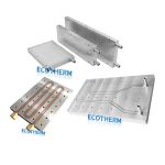
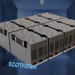
| Active Liquid Cooling | Uses a pump and cold plate to circulate coolant. | 500W – 3000W+ | < 0.05 | High-density AI servers, HPC clusters, EV battery packs. |
Manufacturing Technologies for Advanced Heat Sink Cooling Systems
The manufacturing process directly dictates the thermal performance and cost of the heat sink.
Aluminum Extrusion: Cost-effective for low-TDP applications. However, fin aspect ratios are limited (typically 10:1 to 20:1), making them unsuitable for extreme power density.
Skived Fin Technology: Precision cutting creates extremely thin fins (down to 0.1mm) from a single block of metal. This yields zero interfacial thermal resistance and allows for massive fin density, making it ideal for forced-convection 300W+ applications.
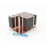
Vapor Chamber Integration: For chips exceeding 400W, a hollow, vacuum-sealed copper chamber filled with a working fluid is used as the base. It instantly vaporizes and condenses, acting as the ultimate heat spreader before handing the heat off to zippered fins.
Frequently Asked Questions (FAQ)
You must use the formula: theta SA = ((Tmax – Tambient) / Power) – theta JC – theta TIM.
To determine how efficient your heat sink needs to be, subtract the maximum ambient temperature from the maximum safe junction temperature of your chip. Divide that number by the total watts dissipated. Finally, subtract the internal chip resistance and thermal paste resistance. The resulting number is the target thermal resistance your heat sink must achieve to prevent failure.
A heat sink is a single component, while a heat dispersal system is the entire thermal assembly. A “heat sink” typically refers to the physical metal structure (the fins and base). A “heat dispersal system” encompasses the broader thermal solution, which may include the heat sink, thermal interface materials (TIM), heat pipes, cooling fans, and the chassis airflow baffling working together to eject heat from the environment.
No, excessively high fin density can ruin cooling performance in air-cooled systems.
While more fins provide more surface area for heat dissipation, they also drastically increase aerodynamic impedance (airflow resistance). If the fins are too close together, a standard fan cannot push air through the narrow gaps. The air will bypass the heat sink entirely, leading to catastrophic overheating.
Use copper for rapid heat absorption at the base, and aluminum for lightweight, cost-effective fins.
Copper has superior thermal conductivity (~390 W/m·K) but is heavy and expensive. Aluminum is cheaper, much lighter, and dissipates heat into the air efficiently. The most optimal B2B engineering solution for high-TDP components is often a hybrid: a solid copper base (or Vapor Chamber) to absorb heat, soldered to aluminum zipper fins for massive surface area.
Liquid cooling is generally required when a single chip’s TDP exceeds 500W-700W.
While advanced air cooling (vapor chambers + high RPM fans) can theoretically handle up to 600W, the noise levels, physical size, and power consumption of the fans become unsustainable. For components like NVIDIA H100 GPUs (700W+) or dense server racks exceeding 40kW total, Direct-to-Chip (D2C) liquid cold plates become mandatory.
Yes, black anodizing significantly improves radiative heat transfer in passive systems.
In active systems with strong fans, convection dominates, and surface color matters little. However, in passive, fan-less environments (like telecom boxes), thermal radiation accounts for up to 30% of cooling. Bare aluminum has an emissivity of about 0.05, while black anodized aluminum has an emissivity near 0.85, making it vastly superior at radiating heat away.