
Custom IGBT Heat Sinks & Power Module Cooling Solutions
High-power Insulated-Gate Bipolar Transistors (IGBTs) are the beating heart of modern power electronics. Whether deployed in industrial motor drives, Energy Storage Systems (ESS), or High-Voltage Direct Current (HVDC) transmission, IGBTs operate under extreme voltages and high switching frequencies.
The Achilles’ heel of any power semiconductor module is overvoltage and overheating. If localized hot spots generated by high power densities are not dissipated instantly, the Junction Temperature (Tj) will breach the critical 150°C threshold, triggering thermal stress failure and short circuits. Ecotherm approaches thermal management from the fundamental Thermal Resistance Model (Rth), engineering custom metal heat sinks and liquid cold plates specifically for high-power IGBT modules.
1. Deconstructing the Thermal Resistance Model: Rja = Rjc + Rcs + Rsa
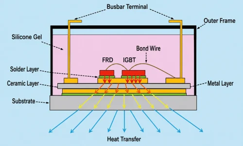
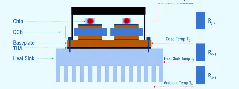
Effective IGBT thermal management requires more than just bolting on a piece of aluminum. It requires precise intervention along the entire heat transfer path—from the silicon die to the ambient environment. The total junction-to-ambient thermal resistance (Rja) consists of three main components:
Rjc (Junction-to-Case): Heat transfers downwards from the Si/SiC chip, through the solder layer, the Copper (Cu) trace, the insulating substrate (e.g., Al2O3 or AlN), and finally to the copper baseplate.
Rcs (Case-to-Sink): The contact thermal resistance between the IGBT’s copper baseplate and the external heat sink.
Rsa (Sink-to-Ambient): The resistance of the heat sink itself in transferring heat to the cooling medium (air or liquid).
Typical Thermal Conductivity of Internal IGBT Components (For Simulation Reference):
| Component | Typical Material | Thermal Conductivity (W/m·K) | Typical Thickness (μm) |
| Chip (Die) | Si / SiC | ~ 130 – 150 | 96 |
| Die Attach | Tin-Silver Solder | 57 | 110 |
| Insulating Substrate | $Al_2O_3$ Ceramic | 24 | 380 |
| Baseplate | Pure Copper | 380 | 3000 |
Ecotherm’s core manufacturing capabilities focus on drastically reducing the external Rcs and Rsa to provide quantifiable cooling improvements.
2. Conquering Rcs: Mounting Pressure, Flatness, and High-Performance TIM
The presence of micron-level air gaps between an IGBT copper baseplate and a metal heat sink is fatal to the system. The thermal conductivity of air is a mere 0.025 W/m·K, acting as a severe thermal insulator.
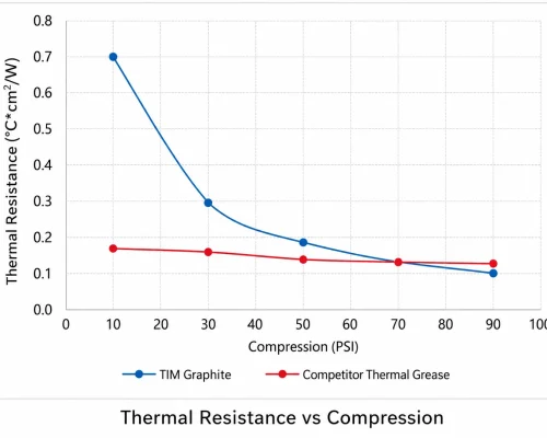
To minimize contact thermal resistance, Ecotherm employs high-precision CNC face milling on the heat sink base, ensuring exceptionally low surface roughness and micron-level flatness. Under a standard 70 PSI mounting pressure, combined with a ~200μm layer of high-performance Thermal Interface Material (TIM, yielding 0.8–4 W/m·K), we effectively purge the trapped air. This increases the interfacial heat transfer efficiency by orders of magnitude, causing an exponential drop in Rcs.
3. Advanced IGBT Heat Sinks & Cold Plate Technologies
We engineer tailored thermal solutions for various power device topologies, including standard modules, Direct Liquid Cooling (DLC), Double-Sided Cooling (DSC), and Press Pack IGBTs (PPI):
A. Embedded Heat Pipe Sinks
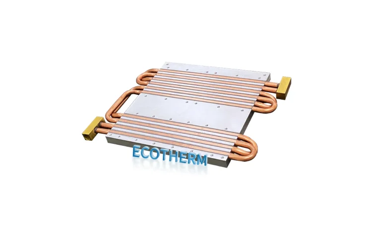
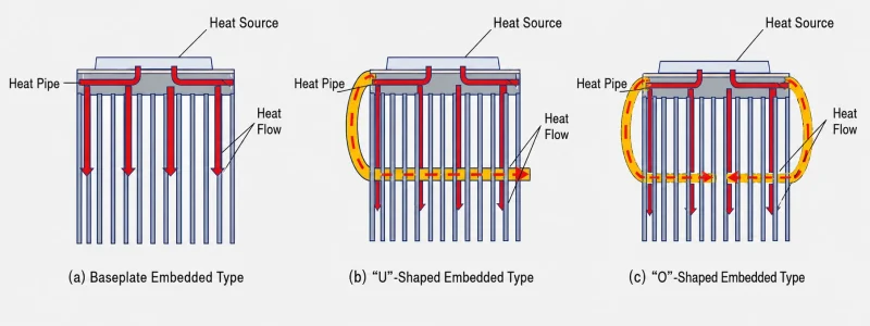
For highly concentrated single-point IGBT modules, the perimeter fins of a standard extruded heat sink often remain thermally underutilized. We CNC-machine precise grooves into the metal baseplate to embed high-conductivity heat pipes using thermal epoxy or mechanical pressing.
U-Shape vs. O-Shape Layouts:
Our thermal simulations and empirical testing reveal that both “U” and “O” shaped heat pipe layouts significantly increase the heat flux density across the lower and middle fin sections.
Notably, the “O” shape layout demonstrates superior isothermal performance (even heat spreading), effectively reducing the peak baseplate temperature by up to 20°C.
B. Custom Liquid Cold Plates
When power dissipation reaches the megawatt (MW) level, forced air cooling hits its physical limitations. The heat transfer coefficient of liquid cooling is generally 100 to 300 times greater than that of natural convection.
Vacuum Brazing & Friction Stir Welding (FSW): We utilize flux-free vacuum brazing to manufacture cold plates with precise internal fluid channels for high-density power modules. For massive, multi-module arrays, we employ solid-state FSW to guarantee 100% leak-proof performance even under extreme system water pressures.
(Note: To explore our fluid routing structures, visit our custom liquid cold plates page.)
C. Press Pack IGBT (PPI) Cooling Assemblies
For high-capacity PPI modules used in Voltage Source Converter (VSC) HVDC transmission, systems demand failure-short-circuit capabilities and double-sided cooling. Ecotherm custom-manufactures robust double-sided pure copper or aluminum cold plates designed to withstand extreme mechanical clamping pressures, ensuring absolute electrical and thermal stability.
4. What to Include in Your RFQ (Early-Stage Designs Welcome)
Designing a reliable heat sink for high-power IGBT modules is a collaborative process. Whether you have a fully finalized design or just a rough thermal concept, our engineering team is here to help.
To help us provide the most accurate Design for Manufacturability (DFM) review and quotation, it is helpful to share as much of the following information as you currently have:
Mechanical Constraints: 2D/3D drawings (STEP/IGES) or simply the maximum available space and mounting footprint.
Thermal Targets: Estimated power loss (W) per module and the target maximum junction temperature ($T_j$).
Coolant Preferences (If applicable): Expected coolant type and any strict limits on flow rate (LPM) or pressure drop ($\Delta P$).
Application Environment: Any specific requirements for insulation, corrosion resistance, or surface treatments.
Don’t have all the parameters locked down yet? No problem.
Send us your preliminary layout and heat load data. The Ecotherm thermal engineering team will work directly with you to calculate the missing variables and recommend the most cost-effective cooling structure.