Inverter Heat Sink & IGBT Cooling Solutions
Inverter heat sink design is critical for keeping IGBT, MOSFET, and power modules within a safe operating temperature range. A well-engineered cooling structure reduces thermal resistance, protects junction temperature, and helps high-power inverters operate steadily under peak loads.
Ecotherm Group manufactures custom inverter heat sinks, IGBT cooling modules, and liquid cold plates for solar inverters, EV motor controllers, charging stations, and industrial power electronics.
We strictly manufacture the thermal components based on your engineering drawings.
Custom Inverter Heat Sinks for Power Electronics
An inverter heat sink is not just a piece of aluminum with fins. It must match the power module layout, heat load, mounting surface, airflow path and available space.
01
IGBT modules
02
MOSFET power modules
03
Solar inverters
04
Wind power converters
05
PCS units
06
VFD systems
07
Motor drives
08
EV traction inverters
09
Industrial power supplies
10
High-power test equipment
Depending on the power level and structure, the design may use an air-cooled heat sink, skived heat sink, bonded fin heat sink, heat pipe assisted heat sink or liquid cold plate.
Where Heat Comes From in an Inverter
The main heat sources in an inverter are power semiconductor devices and magnetic components. IGBT modules and MOSFETs generate heat during switching and conduction.
For IGBT modules, the heat mainly comes from two types of loss:
| Heat Source | What It Means | Design Impact |
|---|---|---|
| Conduction loss | Heat generated when current flows through the device | Depends on current, duty cycle and module characteristics |
| Switching loss | Heat generated during turn-on and turn-off events | Increases with switching frequency, current and bus voltage |
| Magnetic component loss | Heat from inductors, transformers and other magnetic parts | Requires airflow, heat spreading or local heat sinking |
| Contact loss | Heat trapped by poor contact between module and heat sink | Requires flat surface, correct TIM and proper mounting pressure |
A good inverter cooling design starts with the actual power loss, not only the rated power of the inverter.
The primary heat sources are power semiconductor devices (IGBTs) and magnetic components (inductors, transformers). For IGBT modules, heat generation comes from two major losses:
1. Conduction Loss Heat is generated by internal resistance (saturation voltage drop) when current flows through the device. Simplified expression: Pcond = VCE(sat) × Ic × D
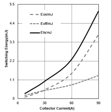
2. Switching Loss When the IGBT turns on and off at high frequencies, voltage and current overlap, creating transient energy spikes. Simplified expression: Psw = (Eon + Eoff) × fsw
1. Conduction Loss
Heat is generated by internal resistance (saturation voltage drop) when current flows through the device. Simplified expression: Pcond = VCE(sat) × Ic × D
2. Switching Loss
When the IGBT turns on and off at high frequencies, voltage and current overlap, creating transient energy spikes. Simplified expression: Psw = (Eon + Eoff) × fsw
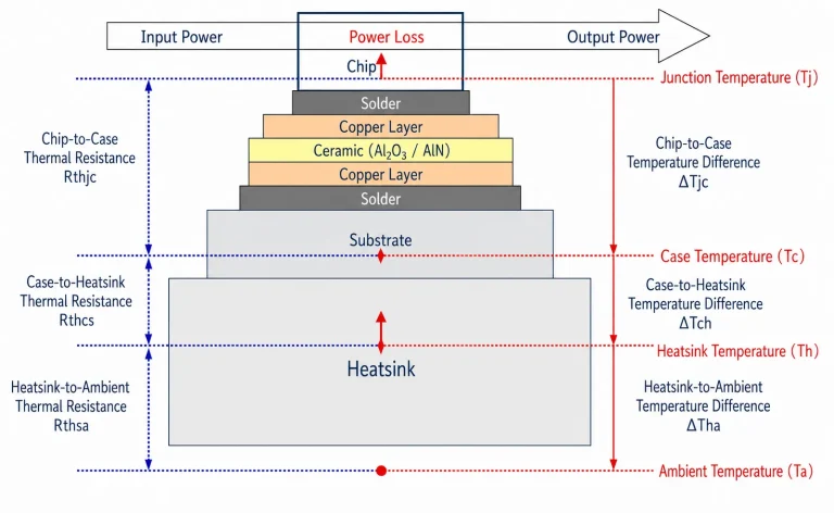
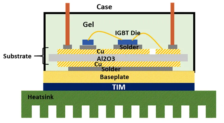
IGBT Thermal Path: From Junction to Heat Sink
IGBT heat must travel through a three-level thermal resistance path before it reaches the ambient air or coolant.
| Thermal Resistance | Meaning | What Affects It |
| Rth,jc | Junction-to-Case | Chip size, solder layer, packaging material |
| Rth,cs | Case-to-Heat Sink | Thermal Interface Material (TIM), surface flatness |
| Rth,sa | Heat Sink-to-Ambient | Fin area, airflow, sink material, coolant flow |
Engineers calculate the junction temperature using:
Tj = Tc + PD × Rth,jc
To ensure maximum reliability, engineers typically utilize an 80% derating rule, aiming to keep the working junction temperature below 120°C for a 150°C-rated component.
Air-Cooled Inverter Heat Sinks
Air-cooled aluminum heat sinks remain the most cost-effective solution for low-to-medium power inverters (e.g., string solar inverters). Aluminum offers an excellent balance of thermal conductivity, lightweight characteristics, and CNC machinability.
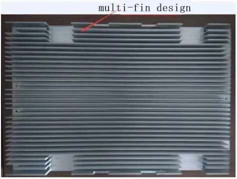
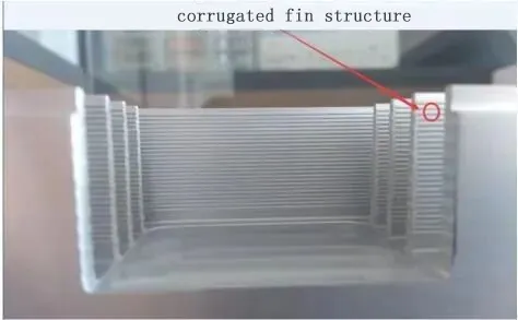
To maximize the convective heat transfer area without increasing the overall volume, advanced air-cooled designs utilize high-density corrugated fins and multi-fin structures.
Key Design Factors for Air Cooling:
Surface Flatness: The IGBT mounting surface must be perfectly flat to eliminate insulating air gaps.
Fin Geometry: Fin thickness and spacing dictate airflow resistance and structural integrity.
Surface Treatment: Black anodizing improves thermal radiation and corrosion resistance.
Liquid Cold Plates for High-Power Inverters
When inverter capacities scale up (e.g., EV motor controllers, central solar inverters), air cooling reaches its physical limits. Liquid cooling transfers heat via a pumped water-glycol mixture, dramatically reducing the spatial footprint.
Optimizing the Liquid Channel (Series vs. Parallel):
The internal flow channel design dictates system energy efficiency. Recent engineering simulations show that while series channels provide consistent temperature distribution, they create massive pressure drops. Conversely, a parallel flow channel design yields a Coefficient of Performance (COP) up to 5 times greater than a series design, saving significant pump power.
Pin-Fin Direct Cooling:
For high-density modules, Pin-Fin baseplates allow the liquid coolant to directly wash over the heat source, eliminating the thermal resistance of traditional thermal grease (TIM).
Double-Sided Cooling for IGBT Power Modules
Traditional IGBT packaging removes heat from only one side (the bottom DBC substrate).
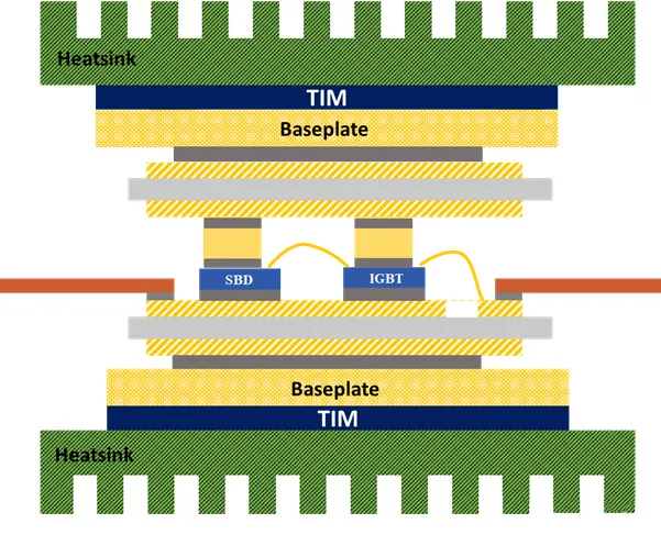
For next-generation EV traction inverters, double-sided cooling is adopted. This planar packaging eliminates traditional wire bonds and dissipates heat from both the top and bottom of the chip simultaneously. It theoretically reduces thermal resistance by up to 50% and improves power cycling reliability by an order of magnitude.
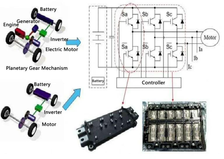
EV Inverter Cooling Applications
In an electric vehicle, the inverter is the core of the Motor Control Unit (MCU). It typically consists of 6 IGBT modules arranged to invert DC battery power into 3-phase AC power for the motor.
Because the IGBT module accounts for roughly 10% of the EV’s total cost and 20% of a charging station’s cost, its thermal stability directly dictates the performance and safety of the entire electric drive system. Liquid cold plates are standard for these high-stress applications.
What Data Should You Send for a Custom Quote?
To design and quote a reliable custom inverter heat sink, Ecotherm requires the following engineering data:
| Required Data | Example / Details |
| Inverter Type | Solar inverter, EV motor controller, UPS |
| Power Loss / Heat Load | Watts (Total loss or per-module loss) |
| Module Layout | 2D drawing, 3D STEP file, mounting hole locations |
| Max Temperature Limit | Allowable junction (Tj) or case (Tc) temperature |
| Cooling Medium | Airflow (CFM) or Coolant (Flow rate & type) |
| Max Pressure Drop | kPa or Bar (for liquid cold plates) |
| Flatness Requirement | e.g., ≤ 0.02 mm per 100 mm |
| Production Quantity | Prototype (Low MOQ), Pilot run, or Mass production |
Send your drawings to our engineering team for a free manufacturability and thermal feasibility review.
FAQ About Inverter Heat Sinks
Can Ecotherm manufacture cold plates from my CAD drawings?
Yes. Ecotherm specializes in custom B2B manufacturing. We produce extruded heat sinks, skived fins, and friction stir welded (FSW) liquid cold plates exactly to your technical drawings, supporting low MOQs for prototyping.
When should an inverter use liquid cooling?
Liquid cooling is mandatory when high-power density (such as in EV traction inverters or megawatt wind converters) makes air cooling geometrically impossible, or when strict junction temperature control is required in compact spaces.
Why is baseplate flatness critical?
Poor flatness creates microscopic air gaps between the IGBT module and the heat sink. Since air is an insulator, these gaps cause massive thermal resistance spikes and local hot spots, even when high-quality thermal paste is used.
What is an inverter heat sink?
An inverter heat sink is a customized metal component (usually aluminum or copper) designed to absorb and dissipate heat generated by IGBTs, MOSFETs, and diodes inside power electronics.