
The Thermal Bottleneck in Industrial VFDs
Variable Frequency Drives (VFDs) and high-voltage inverters are the backbone of modern industrial automation, driving everything from heavy-duty centrifugal pumps to precision CNC machinery. However, power conversion comes with a thermal cost. During operation, high-frequency switching in the internal IGBT modules converts approximately 2% to 5% of electrical energy into waste heat.
For example, a 55kW VFD operating at full load can generate nearly 2,000 kcal of heat per hour. When multiple VFDs are installed inside a sealed industrial control cabinet, they create a severe “oven effect.” Without high-performance VFD heat sinks, cabinet temperatures can quickly exceed the safe operating threshold of 60°C, leading to thermal derating, accelerated insulation aging, and catastrophic drive failure.
At Ecotherm, we specialize in engineering and manufacturing robust custom heat sinks and liquid cold plates for Project Engineers and Sourcing Managers in the industrial, telecom, and medical sectors.
2. Advanced Air Cooling: Maximizing Convection in Control Cabinets
For low to medium-power VFDs, forced air cooling utilizing optimized aluminum heat sinks remains the most cost-effective and reliable solution. We provide high-density thermal solutions designed to conquer cabinet space constraints:
Massive Skived Fin Heat Sinks (Up to 3 Meters):
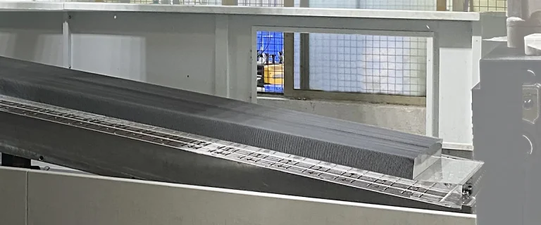
Traditional extrusion processes are limited by die sizes. Ecotherm boasts the advanced manufacturing capability to produce continuous skived fin heat sinks up to 3 meters in length. This provides an unbroken, ultra-high-density fin structure ideal for massive control cabinets and multi-drive setups, ensuring zero interfacial thermal resistance between the base and the fins.
Surface Treatment for Enhanced Radiation:
A raw aluminum finish is not optimal for industrial drives. By applying electrophoretic black paint or black anodizing to our VFD heat sinks, we increase heat dissipation by 10% to 15% in natural convection and 20% to 30% in forced air environments. Furthermore, these treatments enhance dielectric strength, providing surface voltage resistance of 500V to 800V to prevent arcing in compact electrical clearances.
3. Liquid Cooling for Megawatt (MW) High-Voltage Inverters
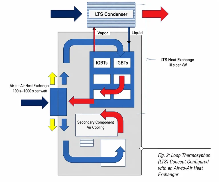
When industrial VFDs scale into the Megawatt (MW) range—commonly found in oil & gas, mining, and heavy automation—air cooling hits a physical wall. Massive airflows draw in abrasive dust, metallic particles, and corrosive gases, severely reducing drive lifespan.
For extreme power densities, Ecotherm manufactures industrial-grade liquid cold plates using vacuum brazing and Friction Stir Welding (FSW) technologies.
Why Transition to Liquid Cooled VFDs?
| Feature | Traditional Air-Cooled VFD | Liquid-Cooled VFD Cold Plate |
| Volumetric Size | Requires massive cabinet space for fins and fans. | 80% smaller footprint (1/5 the size of air-cooled equivalents). |
| Environmental Protection | Requires open ventilation (IP20 to IP54), exposing electronics to dust. | Fully sealed (IP65+), isolating sensitive IGBTs from harsh factory environments. |
| Thermal Efficiency | Limited by ambient air temperature and altitude. | Highly stable coolant loop capable of absorbing massive MW-level heat fluxes. |
4. The Critical Role of Assembly and TIM
A high-performance VFD heat sink is only effective if the thermal interface is optimized. The contact area between the IGBT power module and the heat sink base is where the most critical thermal resistance ($R_{cs}$) occurs.
Ecotherm utilizes precision CNC face milling to achieve micron-level flatness on all heat sink bases. When paired with a meticulously applied, ultra-thin layer of high-quality Thermal Interface Material (TIM), this precision fit reduces interfacial thermal resistance by 25% to 30%. We also advise on optimal layout strategies—such as centering single modules or evenly distributing multiple IGBTs—to ensure uniform torque and prevent mechanical stress during installation.
How We Engineer Your VFD Heat Sink
Step1
Free Thermal Feasibility Analysis
Send us your IGBT module drawings (DXF, STEP, or PDF). Our engineering team performs:
- Thermal simulation — FEA-based junction temperature prediction
Heat sink optimization — fin geometry, material, surface treatment - Cooling method recommendation — air, heat pipe, or liquid
CAD model proposal with integration dimensions
Step2
Custom Design & Prototyping
| Service Phase | Delivery & Specifications |
| Engineering Design | Free thermal simulation & structural analysis |
| Rapid Prototyping | 2–3 weeks for CNC-machined physical samples |
| Order Flexibility (MOQ) | 1 piece for prototyping; flexible volume for production |
| Quality & Testing | Thermal resistance measurement, pressure testing (liquid), and flatness inspection |
Step3
Production & Quality
- ISO 9001 quality system – CMM inspection for critical dimensions
- Surface flatness ≤ 0.1 mm verified – Thermal resistance tested per MIL-STD
- Black anodizing available to improve radiative heat transfer by 20–30%