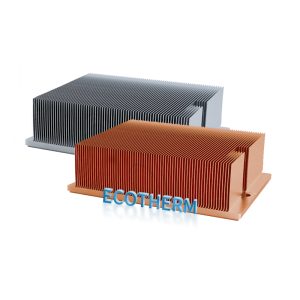
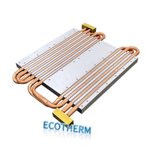
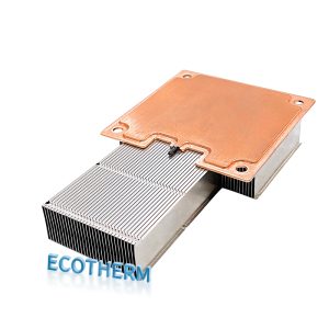
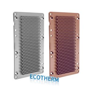
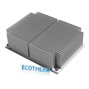
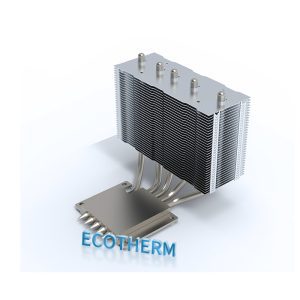
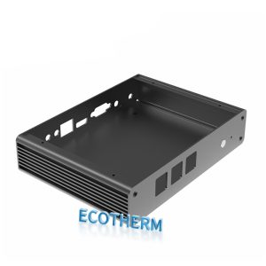
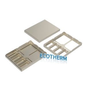
CUSTOM HEAT SINK, PERFECTED FOR YOU.

IGBT Loss & Junction Temperature Calculator

Power module thermal sizing tool

IGBT Loss & Junction Temperature Calculator

Estimate IGBT and freewheeling-diode conduction/switching losses from datasheet parameters, then check steady-state junction temperatures and the cooling resistance required from a cold plate, heat pipe module or skived heat sink.

2-LEVEL PWM · STEADY STATE
1Operating pointCurrent, voltage and PWM
2Datasheet valuesOn-state curves and energies
3Thermal pathJunction, interface and cooler
4Selection resultTemperature and cooling margin

1 · Inverter operating point

Values for one cooled assembly
A RMS
Sinusoidal peak current is calculated as √2 × RMS.
V
kHz
Use the signed displacement power factor.

2 · Datasheet loss parameters

Prefer curves at the intended junction temperature

IGBT IGBT chip position

V
mJ
mJ
°C/W

FWD Freewheeling diode position

V
mJ
°C/W
Switching-energy reference and correction
V
A
%
For gate resistance, temperature and tolerance.
Use 1.0 if only one datasheet test point is known.

3 · Thermal path and cooling candidate

Steady-state screening
°C
°C/W
°C/W
Equivalent common resistance based on total assembly loss.
°C
%

Cold plate check: Use inlet coolant temperature and a cold-plate base-to-coolant thermal resistance at the intended flow. Pressure drop and coolant outlet rise must be checked separately.

Cooling selection result

Three-phase 6-pack · Cold Plate

Candidate passes
Total semiconductor lossEntire cooled assembly
Required heat rejectionIncludes entered thermal design margin
Estimated maximum junctionHottest chip type
Maximum allowable cooler RθFrom cooler base to reference fluid/air

Loss distribution for the complete assembly— W
IGBT conduction IGBT switching FWD conduction FWD recovery
Steady-state thermal path—°C margin
Reference
Cooler base
Module case
IGBT junction
FWD junction
Peak phase current
Loss per IGBT/FWD position
Cooler Rθ margin
Max cooler-base temperature
IGBT loss per position
FWD loss per position
Cold Plate: this result evaluates thermal resistance only. Confirm coolant type, inlet temperature, flow, outlet temperature, internal pressure drop, pump curve and mounting flatness before final sizing.
Screening boundary: use datasheet curves at the intended junction temperature and gate resistance. The model assumes sinusoidal current, two-level PWM, linear voltage scaling and adjustable current scaling of switching energies. It does not replace manufacturer loss simulation, transient Zth analysis, current ripple, dead-time analysis, chip-to-chip coupling or prototype temperature measurement.
Scroll to Top

contact Ecotherm

We are available to assist you via email. Please don’t hesitate to get in touch, and we will respond to your inquiry as soon as possible.


Email:  support@ecothermgroup.com

Follow us on YouTube | TikTok | LinkedIn
Stay connected with us for updates, news, and more!


Please fill out the form below, and we will get back to you as soon as possible.

support@ecothermgroup.com

Contact Ecotherm

Please upload your design or requirements, and our experts will provide a precise cooling solution tailored to your needs.