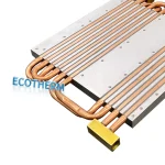
Vapor Chamber Cooling Design Guide for Custom Heat Sinks
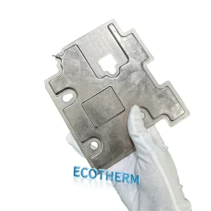
When electronic devices run hotter, standard heat sinks can struggle to move heat away quickly enough, which can reduce performance and shorten product life. Vapor chamber cooling provides an effective way to spread heat evenly and improve thermal control in custom heat sinks. This guide covers the key design points you need to build a more efficient cooling solution from Ecothermgroup.
Takeaway
- Use vapor chambers when you need to spread heat quickly across a custom heat sink and reduce hot spots before the heat reaches fins or other dissipation features.
- Define the thermal target, size constraints, and power density requirements first, since these determine the chamber thickness, footprint, wick structure, and mounting strategy.
- Match the chamber design to the heat source layout: place the evaporator area directly over the hottest components and make sure the spreader can cover the full load distribution.
- Account for orientation, gravity, and working-fluid limits during design, because performance can change significantly with mounting direction and operating temperature range.
- Design the interface carefully by minimizing contact resistance, using flat mating surfaces, and applying consistent clamping pressure with the right TIM.
- Integrate the vapor chamber early with the full thermal stack-up, including fins, heat pipes, airflow, and enclosure constraints, to avoid bottlenecks after fabrication.
- Apply vapor chamber cooling where compact, high-power electronics need even heat spreading, such as GPUs, telecom gear, industrial controllers, and dense power modules.
Vapor Chamber Cooling Basics
Vapor chamber cooling is a two-phase cooling method that helps custom heat sink designs move heat away from a small, concentrated hot spot. In a vapor chamber heat sink, the chamber serves as a vapor chamber heat spreader, so heat does not stay trapped under one device area. This is useful in CPUs, GPUs, power modules, and AI servers, where high heat flux can quickly create hotspots and increase junction temperature. In practice, Ecothermgroup and other thermal designers often pair a custom vapor chamber with fins or fans, because the chamber spreads heat but does not release it to ambient on its own.
How Vapor Chambers Work
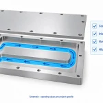
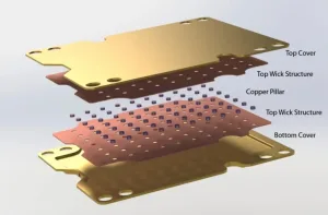
A custom vapor chamber is a sealed, flat metal enclosure with a small amount of working fluid and a wick structure inside. When heat enters one side, the fluid boils, moves as vapor across the chamber, then condenses in cooler areas. The wick pulls the liquid back by capillary action, which is why phase change cooling can transfer heat laterally so effectively in a planar heat pipe or flat heat pipe format. Compared with a simple solid plate, this process lowers spreading resistance and makes the surface temperature more uniform.
Designers still need to respect operating limits. If the heat load is too high, or if the wick cannot return enough liquid, dry-out can occur and performance can drop quickly. Orientation also matters, because gravity can help or oppose return flow depending on the layout. A good thermal solution starts with the correct footprint size, thickness, and contact pressure, plus a flat mounting surface to reduce interface resistance.
| Design Factor | Why It Matters |
|---|---|
| Footprint match | Helps the vapor chamber cover the full heat source and spread heat evenly |
| Thickness choice | Affects spreading performance, package height, and chamber strength |
| Flatness and pressure | Reduces thermal interface loss and improves contact |
| Orientation | Supports stable return flow in two-phase cooling |
Vapor Chamber vs Heat Sink and Heat Pipe
A conventional heat sink mainly moves heat into fins and air, while a vapor chamber cooling design first spreads heat across a larger base area. This is why vapor chamber cooling often works better than a metal base alone in compact electronics with concentrated heat sources. It is also more uniform than a straight heat pipe when the goal is wide-area spreading under a flat component footprint. Industry testing and engineering practice often show that vapor chambers are preferred in high heat flux cases where a normal base plate would create a hot center.
| Option | Main Strength | Best Use |
|---|---|---|
| Heat sink base | Simple, low cost | Lower heat density designs |
| Flat heat pipe / planar heat pipe | Moves heat along a path | Narrow or directional layouts |
| Custom vapor heat sink | Spreads heat across a wide area | Small hot spots and tight packages |
For selection, a simple rule helps: use a vapor chamber thermal solution when the heat source is small, the power is high, and the downstream fins need a larger, more even heat load. Use a standard heat sink when the heat is lower and the budget is tighter. A brief checklist can help during design review:
- Match chamber size to the chip footprint
- Check dry-out risk at peak load
- Verify mounting flatness and pressure
- Confirm airflow or fan support
- Validate performance with thermal testing
Safety note: custom vapor chamber assemblies should be verified under real operating temperature, orientation, and load conditions before production use.
Design Goals for Custom Heat Sinks
The main goal of vapor chamber cooling in custom heat sinks is to reduce thermal resistance from the device to the fins and then to ambient air. In practice, a vapor chamber heat sink is chosen when a small hotspot creates uneven heat flow that a simple base plate or flat heat pipe cannot spread effectively. This matters in CPUs, GPUs, power modules, and AI servers, where heat density continues to rise. For example, many server and semiconductor designs now use a custom vapor chamber because it improves temperature uniformity across the base and helps the fin stack work more efficiently.
Designers also need a balanced target, not just the lowest possible temperature. A vapor chamber thermal solution must fit cost, size, weight, and assembly limits. Ecothermgroup and other engineering teams often treat this as a tradeoff problem: if the chamber is too thick or too large, it may cool well but still fail the package layout. If it is too small, the hotspot may remain concentrated and reduce performance.
Heat Flux and Hotspot Control
High heat flux is one of the clearest reasons to use vapor chamber cooling. A phase change cooling chamber spreads heat laterally before it reaches the fins, which reduces local peaks at the junction. This is why vapor chamber thermal solution designs are common in high-power semiconductors and AI server cold plates, where airflow may be limited and the load is not evenly distributed. A flat heat pipe can also spread heat, but a vapor chamber heat spreader usually performs better across a wider base area.
| Design goal | Why it matters | Typical result |
|---|---|---|
| Lower hotspot temperature | Protects device junctions | More stable performance |
| Even base temperature | Uses the full fin area | Better heat rejection |
| Low interface resistance | Prevents contact losses | Stronger overall cooling |
For best results, the chamber footprint should match the heat source footprint closely. A mismatch can leave part of the device undercooled, even if the custom vapor chamber itself has strong internal spreading. Good flatness, proper mounting pressure, and the right thermal interface material are standard best practices. In manufacturer testing, poor contact is one of the most common reasons a custom vapor chamber heat sink underperforms.
Space, Weight, and Orientation Limits
Custom heat sink design is also limited by enclosure space and system weight. In compact electronics, a vapor chamber cooling approach often replaces a thicker base because it offers strong spreading in a thin package. That makes it useful in laptops, telecom systems, and EV power electronics, where every millimeter matters. However, the chamber must still leave room for fin height, mounting hardware, and airflow paths.
Orientation is another practical design goal. Unlike a simple metal base, a vapor chamber and other two-phase cooling devices can show some gravity sensitivity, especially in edge cases or over long periods of use. This is usually less severe than with a conventional flat heat pipe layout, but it still needs validation. A good design review should check these points before final release:
- Available height above the board or cold plate
- Mass limit for the final assembly
- Expected mounting angle in real use
- Seal integrity and material compatibility
For safety and reliability, designers should test the custom vapor chamber heat sink in the same orientation, airflow, and contact pressure it will see in the field. That approach gives a more realistic result than bench testing alone, and it helps ensure the final vapor chamber cooling design meets both thermal and mechanical goals.
Key Design Factors
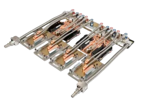
In vapor chamber cooling, the main design goal is not only lower temperature, but better heat spreading inside a custom vapor chamber heat sink. For high heat flux parts such as CPUs, GPUs, power modules, and AI server chips, the chamber helps move heat laterally so the fin stack sees a wider, more even source. This is why many engineers choose a custom vapor chamber when a flat heat pipe or planar heat pipe cannot spread heat well enough in a small envelope.
Wick Structure and Working Fluid
The wick and fluid define the thermal response of any vapor chamber thermal solution. A fine wick can help return liquid quickly, but it must also avoid dry-out as the heat load rises. Copper-water is the common baseline because it is stable and efficient for many electronics, while special environments may require other fluid and material pairs for reliability. In custom designs from Ecothermgroup, this choice is often matched to the target power density and the mounting orientation, since vapor chamber cooling usually performs best when the internal capillary path is balanced with the real use case.
| Design Factor | Why It Matters | Practical Focus |
|---|---|---|
| Wick structure | Controls liquid return and dry-out risk | Match to heat flux and orientation |
| Working fluid | Affects temperature range and reliability | Commonly copper-water for electronics |
| Material pair | Supports long-life sealing | Check compatibility and corrosion risk |
Thickness, Size, and Interface Quality
Thickness and footprint must fit the product envelope, because a vapor chamber heat spreader delivers its best value in limited space. A thinner chamber helps compact systems, but it may reduce vapor space and increase pressure drop, so designers usually balance height against performance. Size also matters: if the chamber is too small for the hotspot, heat spreading is limited; if it is too large, cost and mass rise without a clear gain. Studies and field practice in server and power electronics cooling show that poor flatness or weak contact pressure can erase much of the benefit, so interface quality is a key design factor, not a finishing detail.
- Check flatness before assembly.
- Use the right thermal interface material.
- Verify mounting pressure across the full contact area.
Material Pairing and Reliability
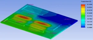
Material pairing affects both thermal performance and service life in two-phase cooling and phase change cooling systems. Copper remains the most common choice because it supports good conductivity and sealing, while aluminum or mixed-metal designs need more care to avoid compatibility issues. Reliability also depends on solder joint quality, leak control, and test validation under thermal cycling. In real deployments, especially for AI servers and EV power electronics, the chamber must work with the fin geometry and airflow path above it; the vapor chamber improves spreading, but it does not replace a well-sized heat sink. For this reason, thermal validation should include hotspot mapping, orientation checks, and long-run stress testing before release.
Integration Best Practices
In vapor chamber cooling, the chamber is usually not the entire solution; it acts as the heat spreader inside a custom heat sink and helps lower hotspot temperatures before heat moves into the fin stack. This matters in CPUs, GPUs, power modules, and AI server boards, where high heat flux can create uneven temperatures even when total power is similar. In practice, a well-designed vapor chamber heat sink can improve temperature uniformity more than a simple flat base, but only if the chamber size, package footprint, and airflow path are matched correctly.
Contact Pressure and Flatness
Good contact is one of the main rules for a custom vapor chamber heat sink. The mating surfaces should be flat and controlled, because even a small gap can add thermal resistance and reduce the benefit of two-phase cooling. Many engineers use a thin TIM layer to fill micro-gaps, but TIM cannot fix a warped base or a poor interface. For example, chamber thickness, lid planarity, and mounting force should be checked together, especially when the heat source is small and the load is concentrated in one area.
| Issue | Common Cause | Best Fix |
|---|---|---|
| Hotspot remains near chip center | Poor flatness or low pressure | Improve surface finish and adjust clamp load |
| Edge temperatures are uneven | Weak spread across the base | Use a larger vapor chamber cooling plate |
| Thermal result changes after cycling | Mounting relaxes over time | Validate torque, spring force, and retention |
As a general rule, designers should compare the full thermal stack-up, not only the vapor chamber thermal solution. Airflow, fin geometry, and base attachment all affect final performance, especially in compact products with limited space. Ecothermgroup often recommends checking contact pressure during both initial assembly and after thermal cycling, since repeated heating and cooling can change clamping behavior.
Mounting, Soldering, and Assembly
Mounting method should match the product environment. A bolted frame works well when serviceability matters, while a soldered or brazed bond can reduce interface resistance in a more permanent assembly. Soldering is common in advanced planar heat pipe and vapor chamber cooling designs because it improves stability, but it also requires careful process control to avoid voids, distortion, or damage to the custom vapor chamber. A well-matched assembly should also respect the chamber orientation, since the heat source footprint and chamber area must work together for even spreading.
- Use controlled torque or spring clips to avoid overloading the package.
- Keep the TIM layer thin and uniform.
- Check that the chamber is fully supported during handling and rework.
In real manufacturing, the safest approach is to verify the assembly method early, not after the full sink is built. That is especially true for a custom vapor chamber heat sink used in high-reliability electronics, where vibration, shock, and service life matter as much as raw thermal performance.
Testing and Thermal Validation
Testing should confirm both heat spreading and mechanical reliability. A practical validation plan compares the vapor chamber heat sink against a baseline flat heat pipe or standard base, then measures junction temperature, spread uniformity, and pressure stability under expected load. In high-power semiconductor and AI server work, engineers often look for lower hotspot rise and more stable behavior under constrained airflow, because these are the real signs that phase change cooling is helping.
A simple validation sequence can be useful:
- Measure flatness, torque, and contact pattern before power testing.
- Run thermal tests at low, medium, and peak load.
- Repeat after thermal cycling to check retention and interface stability.
Common industry practice is to test the whole system, not just the vapor chamber cooling part. That means checking fin stack performance, fan speed, and orientation effects together. For custom heat sinks, this step is critical because a chamber that performs well on the bench may behave differently in a real enclosure with limited airflow. Safety note: if the assembly shows non-uniform contact, visible warping, or rising temperatures after cycling, the design should be corrected before production release.
Applications and Use Cases
Vapor chamber cooling works best when a custom heat sink needs to manage a small, hot source and spread heat across a wider area before it reaches the fins. In practice, a vapor chamber heat sink helps reduce hotspot temperature and improve temperature uniformity, which is why it is often used in compact electronics with high heat flux and limited airflow. In a well-designed vapor chamber thermal solution, the chamber is not the entire answer; it usually works with fins, heat pipes, or forced air to create a complete custom vapor chamber heat sink. Ecothermgroup commonly applies this approach when the thermal target is shaped by footprint, thickness, and reliability limits.
CPUs, GPUs, and AI Servers
For CPUs and GPUs, the main benefit of vapor chamber cooling is lateral heat spreading. This matters because modern processors can create intense local hot spots, and a flat heat pipe or planar heat pipe may not spread heat as evenly across a large base. In AI servers, this need is even greater: recent server designs often deal with very high power density, and thermal teams use vapor chamber heat spreader plates or vapor chamber cold plates to keep junction temperatures under control under constrained airflow. Industry reports on AI servers also show that airflow limits are becoming a major design issue, so a custom vapor chamber can improve performance without making the system much louder.
| Use case | Why vapor chamber cooling fits | Common design pair |
|---|---|---|
| Desktop CPU | Spreads hotspot load across the fin base | Forced air fin stack |
| GPU | Handles high heat flux from a small die area | Vapor chamber heat sink |
| AI server | Supports dense layouts and lower temperature spread | Cold plate or hybrid cooling |
Power Electronics and EV Systems
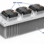
Power modules, inverters, and EV electronics often need a vapor chamber thermal solution because they must stay reliable under repeated thermal cycling. A custom vapor chamber heat sink can reduce temperature rise in compact packages where a solid aluminum base is not enough. For EV systems, the design must also account for vibration, mounting pressure, and packaging space. That is why many engineers compare two-phase cooling options early, then choose vapor chamber cooling only when the heat load and layout justify the added cost and assembly care.
- Best for tight module footprints
- Useful when airflow is weak or uneven
- Helps reduce hotspot stress in solder and TIM layers
Aerospace and Other High-Power Systems
Aerospace electronics, radar units, and other high-power systems often need low mass, stable thermal spreading, and dependable operation across changing orientation. This is one reason vapor chambers are often preferred over a conventional flat heat pipe when the heat source is broad or the device may not stay in one position. For these applications, design checks should include flatness, wick structure, working fluid, and solder joint quality, because small build errors can reduce reliability. A practical rule is to match the chamber size to the heat source footprint and verify contact pressure before release. For high-risk systems, safety testing and thermal validation should always be part of the final design review.
People Also Ask
How does vapor chamber cooling improve the performance of a custom heat sink?
Vapor chamber cooling spreads heat laterally across a much larger area than a solid base, which reduces hotspots and improves temperature uniformity. That makes custom heat sinks more effective when the heat source is small, dense, or unevenly loaded.
When should a design use a vapor chamber instead of a heat pipe?
A vapor chamber is usually the better choice when a design needs strong two-dimensional heat spreading across a flat surface. Heat pipes are often better for moving heat in one direction, while vapor chambers are favored in compact electronics and high heat flux applications.
What design factors matter most in vapor chamber cooling for custom heat sinks?
Key factors include chamber thickness, wick structure, working fluid, flatness, and the quality of the solder or interface layer. These choices affect thermal resistance, spreading performance, and long-term reliability.
What are the most common integration mistakes in vapor chamber heat sink designs?
Common mistakes include poor surface flatness, insufficient contact pressure, and mismatching the vapor chamber size to the heat source footprint. These issues reduce heat transfer efficiency and can erase much of the benefit of vapor chamber cooling.
Is vapor chamber cooling better than a traditional heat sink?
It is often better when the main challenge is spreading heat from a concentrated source before it reaches the fins. A traditional heat sink can still work well for lower-power or more uniform loads, so the best choice depends on the thermal density and package constraints.
What are the main applications of vapor chamber cooling?
Common applications include CPUs, GPUs, power electronics, AI servers, EV components, and aerospace systems. These environments benefit from lower junction temperatures and better thermal spreading under tight space or airflow limits.
Does vapor chamber cooling work well in any orientation?
Vapor chambers are generally less orientation-sensitive than heat pipes because they spread heat across a plane rather than relying on a single flow path. Performance can still vary with design details and operating conditions, so the intended mounting orientation should be validated during testing.
How do you know if a vapor chamber is the right choice for a high-power design?
It is a strong candidate when the design has high heat flux, limited airflow, or a need to equalize temperatures across a baseplate or heat sink. Thermal simulation and prototype testing are the practical ways to confirm that vapor chamber cooling will meet the target junction temperature and reliability requirements.