Vapor Chamber Technical White Paper: Principles, Selection & Applications in Custom Cooling Solutions
Executive Summary
As thermal design power (TDP) of AI accelerators, high-performance computing chips, and wide-bandgap power devices continues to climb, the thermal spreading limitations of traditional solid-copper heatsinks have become increasingly apparent. The vapor chamber (VC) — a passive, two-phase thermal management component — delivers planar heat-spreading capability and effective thermal conductivity orders of magnitude beyond solid copper. It is now accelerating its penetration from niche high-end applications into mainstream industrial and enterprise-grade cooling solutions.
This paper is written for thermal engineers and sourcing decision-makers. It systematically covers VC operating principles, critical design parameters, material and manufacturing process selection, and engineering applications across servers, telecommunications equipment, and power electronics.
1. Operating Principle and Core Advantages
1.1 How a Vapor Chamber Works
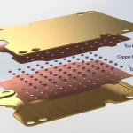
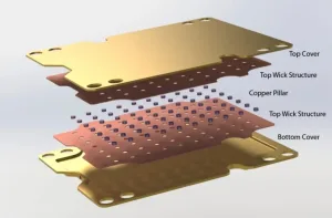
A vapor chamber is a planar heat-spreading device that uses the latent heat of phase change to transport thermal energy. It consists of a vacuum-sealed metal enclosure containing a precisely metered quantity of working fluid (typically deionized water), with a capillary wick structure bonded to the internal walls. The operating cycle has four stages:
- Evaporation: Heat from the source enters through the baseplate. The liquid working fluid within the wick absorbs latent heat and undergoes phase change into saturated vapor.
- Vapor Transport: The vapor rapidly diffuses through the vapor core from the high-pressure region (above the heat source) toward lower-pressure regions (the condenser area).
- Condensation: Vapor contacts the cooler condenser walls, releases latent heat, and condenses back into liquid.
- Liquid Return: Condensed liquid is driven back to the evaporator region by capillary pressure differential within the wick structure, completing the cycle.
A critical design point: the return driving force comes from capillary pressure, not gravity. This means a well-designed VC exhibits far lower orientation sensitivity than gravity-assisted thermosyphons, making it suitable for multi-attitude installations.
1.2 Why a Vapor Chamber Instead of a Thicker Copper Plate?
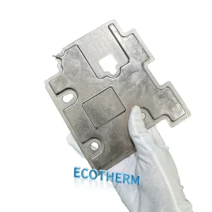
Pure copper has a thermal conductivity of approximately 380–400 W/(m·K). No matter how thick a copper plate is made, its in-plane heat-spreading capacity is fundamentally limited to the product of the material’s intrinsic conductivity and its cross-sectional thickness. The practical problem:
- When the heat source area (e.g., a chip die) is far smaller than the heatsink base area, a solid copper baseplate exhibits a significant spreading ΔT — the region directly above the heat source runs hot, while the baseplate edges contribute little to overall heat dissipation.
- Increasing copper thickness can partially improve spreading, but it brings linear increases in weight and cost, with sharply diminishing returns.
A vapor chamber routinely delivers effective thermal conductivity 10× to 50× that of solid copper, with advanced designs reaching the 10,000–40,000 W/(m·K) range. At equivalent baseplate thickness, a VC can compress hot-spot ΔT to within a few degrees, ensuring the full fin array participates in heat rejection.
In one line: a copper plate “absorbs” heat; a vapor chamber “spreads” it.
2. VC vs. Heat Pipe: Engineering Selection Criteria
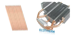
In custom cooling solutions, vapor chambers and heat pipes are complementary, not competing, technologies. The core selection logic:
2.1 Spreading vs. Transport
| Requirement Profile | Recommended Component | Rationale |
|---|---|---|
| Heat source area ≪ heatsink base area (>10:1 ratio), base ΔT > 10°C | Vapor Chamber | 2D planar spreading, superior isothermality |
| Heat must be transported to fin arrays >50 mm from source | Heat Pipe | Higher 1D transport efficiency over distance |
| Multiple dispersed heat sources sharing one heatsink | Vapor Chamber first | Single plate covers all sources; no need to route individual pipes per source |
| Severe Z-height constraints (e.g., 1U server) | Vapor Chamber | Can be compressed to 1–3 mm thickness; flattened heat pipes lose performance at pinch points |
2.2 Hybrid Architectures
In practice, the two are frequently combined:
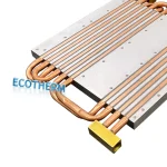
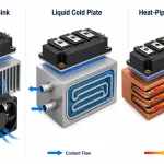
- VC + Embedded Heat Pipes: A VC serves as the heatsink baseplate, receiving heat directly from the chip; heat pipes are soldered to or embedded within the VC to carry heat to remote fin arrays. This architecture addresses both local spreading and long-distance transport.
- VC-ELCC (Embedded Liquid-Cooled Channels): Liquid-cooling channels are integrated within the VC cavity, merging passive phase-change spreading with active liquid cooling. Thermal response time constants can be reduced by 28–41%, making this particularly effective for AI inference workloads with highly dynamic power fluctuations.
2.3 A Practical Rule of Thumb
When heatsink base area exceeds 10× the heat source area, and simulation of a solid copper baseplate shows spreading ΔT > 10°C, introducing a vapor chamber typically yields a 15–30% improvement in total thermal performance.
3. Critical Design Parameters and Performance Metrics
When specifying a custom VC solution, the following parameters are non-negotiable:
3.1 Effective Thermal Conductivity (keff)
This is the most intuitive performance figure. Back-calculated from Fourier’s law, mainstream industrial VCs achieve 3,000–12,000 W/(m·K); high-performance designs exceed 30,000–40,000 W/(m·K).
Important caveat: k_eff is not a material constant. It is an operating-point-dependent parameter that varies with heat flux, fluid fill ratio, and orientation angle. Any quoted k_eff value should be accompanied by its test conditions.
3.2 Thermal Resistance (Rth)
Defined as the temperature difference from evaporator to condenser divided by input power, expressed in °C/W or K/W. High-performance VCs typically operate in the 0.02–0.1 °C/W range. Lower R_th means a smaller temperature gradient for a given heat load.
3.3 Capillary Limit and Dry-out
This is the VC’s power ceiling. When the input heat flux exceeds the wick’s capillary return capacity, the evaporator wick runs dry, the local temperature spikes, and the VC fails. All efforts to raise the capillary limit ultimately trace back to wick optimization — the subject of Section 4.
3.4 Anti-Gravity Performance
When the evaporator is positioned above the condenser (i.e., liquid must return against gravity), the VC’s heat transport capacity degrades. For some designs, performance can drop by more than 30% in adverse orientations. During the design phase, obtain the manufacturer’s performance-derating curves across all intended installation attitudes.
4. Wick Technology: The Heart of the Vapor Chamber
The wick governs capillary return capability and flow resistance — it is the single most critical subsystem. Current mainstream options:
4.1 Sintered Powder Wick
Copper or copper-alloy powder is sintered at high temperature onto the enclosure’s internal walls, forming a porous structure that provides capillary driving force.
- Strengths: High capillary pressure, excellent anti-gravity performance, mature process, proven long-term reliability.
- Weaknesses: Lower permeability; at high power levels, liquid return resistance becomes significant.
- Best for: Low-to-medium power applications with multi-attitude installation requirements.
4.2 Mesh Wick
Multiple layers of copper or titanium mesh are stacked to form capillary flow channels.
- Strengths: Controllable porosity; permeability exceeds sintered powder at equivalent pore size; compressible in thickness — suitable for ultra-thin designs.
- Weaknesses: Contact thermal resistance between mesh and enclosure wall can be difficult to control; soldering process demands are high.
- Best for: Thickness-constrained applications.
4.3 Grooved Wick
Micro-grooves are machined directly into the internal enclosure wall.
- Strengths: High permeability, low liquid-phase resistance — well-suited to high-power, long-distance return paths.
- Weaknesses: Low capillary pressure, poor anti-gravity capability.
- Best for: Horizontal or gravity-assisted orientations.
4.4 Composite / Gradient Wick
This is where active R&D is concentrated. The concept breaks free from single-structure limitations by varying pore size or wick type across different zones:
- Gradient-aperture sintering: Small-pore powder at the evaporator for strong capillary suction; large-pore powder in the condenser and return path to reduce flow resistance.
- Groove + sintered composite: Grooves handle low-resistance transport; a sintered layer provides strong capillary pumping.
- Biomimetic hierarchical structures: Channel designs inspired by leaf venation or fractal branching. One leaf-vein-inspired design (2025) pushed effective thermal conductivity to 43,188 W/(m·K) with thermal resistance of only 0.022°C/W.
For custom cooling solution providers, wick selection is the critical decision that links the customer’s thermal requirements to the product’s achievable performance. Given identical external dimensions, different wick strategies can produce multi-factor performance differences.
5. Material and Manufacturing Process Selection
5.1 Copper-Based vs. Aluminum-Based
| Dimension | Copper-Based | Aluminum-Based |
|---|---|---|
| Thermal performance | Superior | Good (Al bulk conductivity ≈ 60% of Cu) |
| Process maturity | High (sintering, brazing well established) | Rapidly advancing (brazed Al VC is a recent hotspot) |
| Weight | Heavy (8.96 g/cm³) | Light (2.7 g/cm³, ~30% of Cu) |
| Cost | High material cost | Low material cost, but brazing process investment is significant |
| Size capability | Primarily small-to-medium format | Large formats feasible (470×210 mm in volume production) |
| Best for | High-performance, high-reliability applications | Lightweight, large-area, cost-sensitive applications |
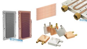
Copper-based VCs remain dominant in high-end servers and base-station equipment. Aluminum-based VCs are gaining rapid traction in telecom cooling, battery thermal management, and laser cooling — applications that demand large surface area and low weight rather than extreme heat-flux capability.
5.2 Ultra-Thin VC Manufacturing Challenges
For VCs below 0.3 mm in thickness, manufacturing complexity rises sharply:
- Vapor core volume is severely compressed, increasing vapor flow resistance and reducing power capacity.
- Enclosure stiffness drops; vacuum-induced deflection becomes a yield issue.
- Support pillar placement and soldering precision requirements become extreme.
- Yield rate is the single largest cost driver in this product category.
When quoting custom ultra-thin VC projects, every 0.1 mm reduction in thickness typically brings a step-function increase in unit price. It is worth advising customers not to chase extreme thinness beyond what the application genuinely requires.
6. Industry Applications and Solution Characteristics
6.1 AI Servers and HPC
Pain point: 400–700 W per chip, multi-GPU side-by-side layouts, tight volumetric constraints, conventional air-cooled baseplates with severe spreading deficiency.
VC solution profile: Large-format copper-based VC as the heatsink baseplate (can span multiple chips); combined with embedded heat pipes or direct-contact liquid-cooling cold plates for secondary heat rejection. Design priority: raising the capillary limit to prevent localized dry-out under asymmetric multi-source loading.
Reference data point: Experimental aluminum 3D-VC heatsinks have demonstrated 0.04°C/W steady-state thermal resistance with >1,000 W maximum cooling capacity.
6.2 Telecom Base Stations
Pain point: Outdoor installation, fully passive (fanless) cooling, high reliability requirements, long service life.
VC solution profile: Aluminum-based large-format VCs preferred to control weight and cost. Anti-gravity performance is a hard requirement (base station mounting orientations vary widely). Strict working-fluid long-term compatibility requirements (10+ year life expectancy).
6.3 Power Electronics and EV
Pain point: IGBT modules, SiC/GaN power devices with extreme heat flux (>150 W/cm²), concentrated hot spots, constrained cooling volume.
VC solution profile: Small-footprint, high-power-density designs. Dry-out margin must be conservatively specified. Must withstand vibration, thermal cycling, and other automotive environmental stresses.
Reference data point: Hierarchical biporous wick VC with superhydrophobic condenser has demonstrated stable heat dissipation >600 W/cm² with 72-hour continuous operation and no performance degradation.
6.4 Lasers and Optoelectronics
Pain point: Heat concentrated at gain medium or pump-source regions; temperature uniformity directly impacts beam quality and wavelength stability.
VC solution profile: Extremely tight isothermality requirements (typically <1–2°C ΔT). Custom non-rectangular form factors frequently needed (annular, irregular contours) to accommodate optical path layouts. TEC (thermoelectric cooler) + VC combination enables precision temperature control.
7. Engineering Workflow for Custom VC Cooling Solutions
A well-structured custom VC project follows this sequence:
- Thermal Requirements Analysis: Determine heat source count, power per source, footprint, allowable junction temperature, ambient temperature range, and installation attitudes.
- Technology Selection: Verify VC is the optimal choice (see Section 2 criteria); define the VC + heat pipe / liquid cooling hybrid architecture.
- Preliminary Design: Specify material, external dimensions, thickness, wick type, working fluid, and fill ratio.
- Simulation Validation: Build a 3D multiphysics coupled model (e.g., COMSOL) incorporating phase-change behavior. State-of-the-art simulation can keep temperature prediction error within ±2%.
- Prototype Fabrication and Testing: Prioritize testing R_th vs. power curves across multiple orientations, dry-out limit, and accelerated-aging reliability.
- Production Process Freeze: Lock wick parameters, fill ratio, and soldering process parameters based on prototype test results.
8. Summary and Outlook
The vapor chamber, as a mature passive two-phase cooling technology, is at an inflection point — expanding rapidly from high-performance niche markets into mainstream industrial applications. Three trends are driving this:
- Relentlessly rising AI chip power has exposed the thermal spreading bottleneck of conventional copper and aluminum heatsinks.
- The maturation of brazed aluminum VC manufacturing has opened up a new product space combining large format, light weight, and acceptable cost.
- Advances in wick design and simulation tooling have substantially reduced the development cycle and trial-and-error cost for custom VC solutions.
For cooling solution integrators, building VC technology into the product portfolio — and developing the selection judgment and custom-design capability to deploy it effectively — is the critical move to capture the AI infrastructure cooling upgrade window over the next 2–3 years.
Technical data sourced from: publicly available academic literature, engineering practice reports, and industry white papers current as of August 2026. Specific product parameters should be verified against supplier-provided measured data.